
Columnar joint sample pasting device

A technology of patch device and columnar joint, applied in the field of columnar joint sample patch device, can solve problems such as affecting the test accuracy, and achieve the effect of ensuring reliability and accuracy and reducing damage

Active Publication Date: 2020-08-28
HOHAI UNIV
View PDF10 Cites 1 Cited by
  • Summary
  • Abstract
  • Description
  • Claims
  • Application Information

AI Technical Summary

Problems solved by technology

How to accurately determine the relative position of the patch along the axial and transverse directions on the surface of the columnar joint sample with weak joint strength, and reduce the damage to the sample during the patching process has become a problem that must be solved in the test preparation stage. will directly affect the accuracy of the test

Method used


Image

  • Columnar joint sample pasting device

Examples


Embodiment Construction

[0013] The present invention will be further described below in conjunction with accompanying drawing.

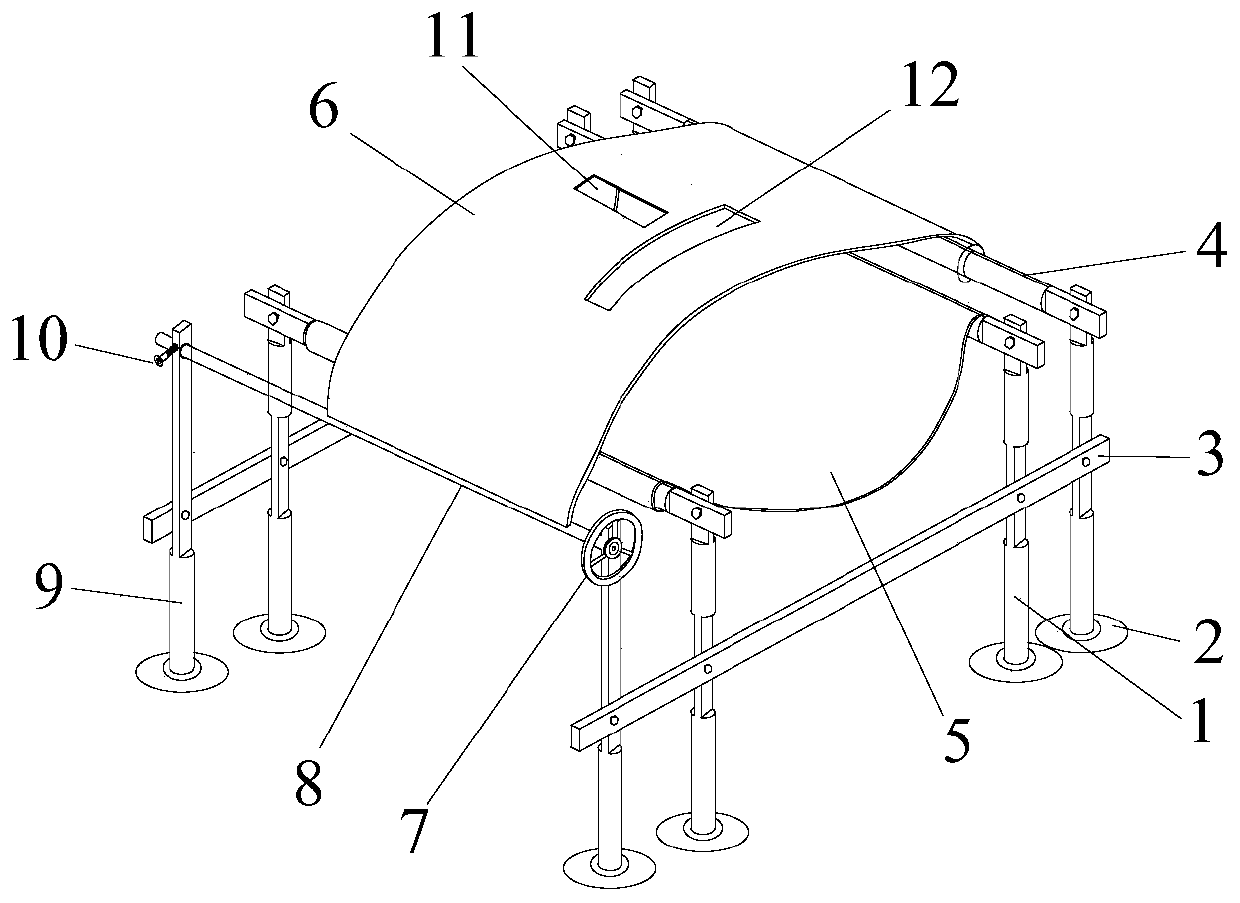
[0014] Such as figure 1 As shown, the bracket and sample constraining structure of the present invention, the bracket includes two groups of symmetrically distributed first lower brackets 1 and second lower brackets 9, wherein the first lower bracket 1 is located inside the second lower bracket 9, and the left side is located The top of one group of second lower brackets 9 is fixed with adjusting rod 8, the top of another group of second lower brackets 9 is connected with upper bracket 4, and the tops of two groups of first lower brackets 1 are connected with upper bracket 4, upper bracket 4 All are detachably connected by bolts. A lower restraint rubber plate 5 is arranged between the two groups of upper supports 4 at the top of the first lower support 1, and an upper restraint rubber plate 6 is arranged between the upper support 4 and the adjusting rod 8 at the top of th...


PUM


Abstract

The invention discloses a columnar joint sample pasting device, which comprises a bracket and a sample constraint structure, wherein the bracket comprises two groups of first lower brackets and two groups of second lower brackets which are symmetrically distributed; the first lower brackets are positioned on the inner side of the second lower brackets; an adjusting rod is fixed at the top part ofone group of second lower brackets; the top part of the other group of second lower brackets is connected with an upper bracket; the top parts of the two groups of first lower brackets are connected with upper brackets; a lower constraint plate is arranged between the two groups of upper brackets located at the top parts of the first lower brackets; an upper constraint plate is arranged between the adjusting rod and the upper bracket located at the top parts of the second lower brackets; the upper constraint plate and the lower constraint plate form the sample constraint structure; and a longitudinal strain gauge pasting opening and a transverse strain gauge pasting opening are formed in the upper constraint plate. According to the columnar joint sample pasting device, a columnar joint sample is fixed by adopting the rubber plates with high flexibility, damage to the sample in the pasting process is reduced, meanwhile, the T-shaped pasting openings with fixed positions are formed, theposition can be fixed, and then the reliability and accuracy of data acquisition are guaranteed.

Description

technical field [0001] The invention relates to a sticking device, in particular to a columnar joint sample sticking device. Background technique [0002] The deformation test of columnar jointed rock mass is an extremely important work in the process of geotechnical engineering construction. The physical model test of columnar jointed rock mass is an important method to predict the deformation law of columnar jointed rock mass. In the laboratory, a high-precision axial differential displacement sensor (LVDT) and a lateral beam-type lateral sensor are used to test the axial and hoop strains. For columnar joint samples, the joints are more developed , the deformation is large, and now the strain gauge is used to replace the previous LVDT and lateral sensor for data acquisition. How to accurately determine the relative position of the patch along the axial and transverse directions on the surface of the columnar joint sample with weak joint strength, and reduce the damage to ...

Claims


Application Information

Patent Timeline
IPC IPC(8): G01N1/28G01N3/02G01N3/06G01N3/08
CPCG01N1/28G01N3/02G01N3/066G01N3/08
Inventor 徐卫亚张涛王环玲黄威胡明涛王伟
Owner HOHAI UNIV
Learn More