Steel pipe bending machining device
A processing device and technology for steel pipes, applied in the field of steel pipe bending, can solve the problems of high labor intensity and limited arm strength, and achieve the effect of reducing labor intensity
- Summary
- Abstract
- Description
- Claims
- Application Information
AI Technical Summary
Problems solved by technology
Method used
Image
Examples
specific Embodiment approach 1
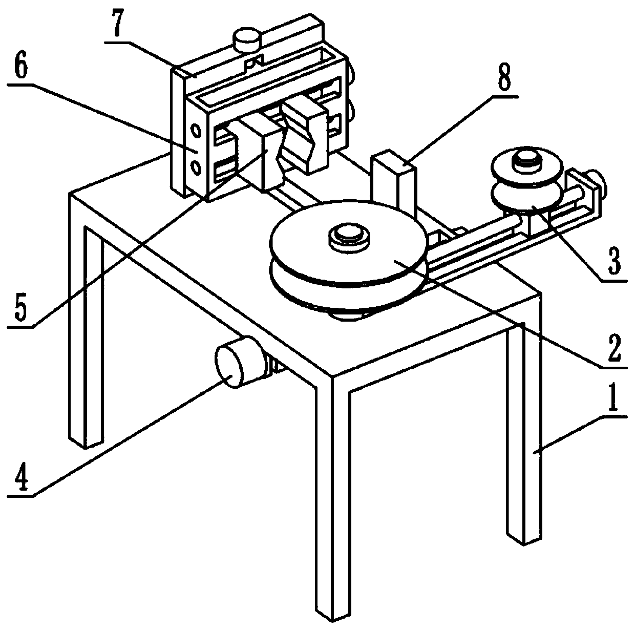
[0030] Such as Figure 1-11 As shown, a steel pipe bending processing device includes a support frame 1, a turret 2, a pipe bending mechanism 3, a pipe bending power mechanism 4, an end fixing mechanism 5, a lifting adjustment mechanism 6, an end adjustment mechanism 7 and an auxiliary blocking mechanism 8. The turret 2 is rotatably connected to the support frame 1, the pipe bending mechanism 3 is connected to the turret 2, the bending power mechanism 4 is connected to the support frame 1, and the bending power mechanism 4 Engaged transmission connection with the turret 2, the end adjustment mechanism 7 is connected to the left end of the support frame 1, the lifting adjustment mechanism 6 is connected to the end adjustment mechanism 7, and the end fixing mechanism 5 is connected to the lifting adjustment mechanism. On the mechanism 6, the described auxiliary blocking mechanism 8 is connected on the support frame 1;
[0031]When in use, press the end of the steel pipe against...
specific Embodiment approach 2
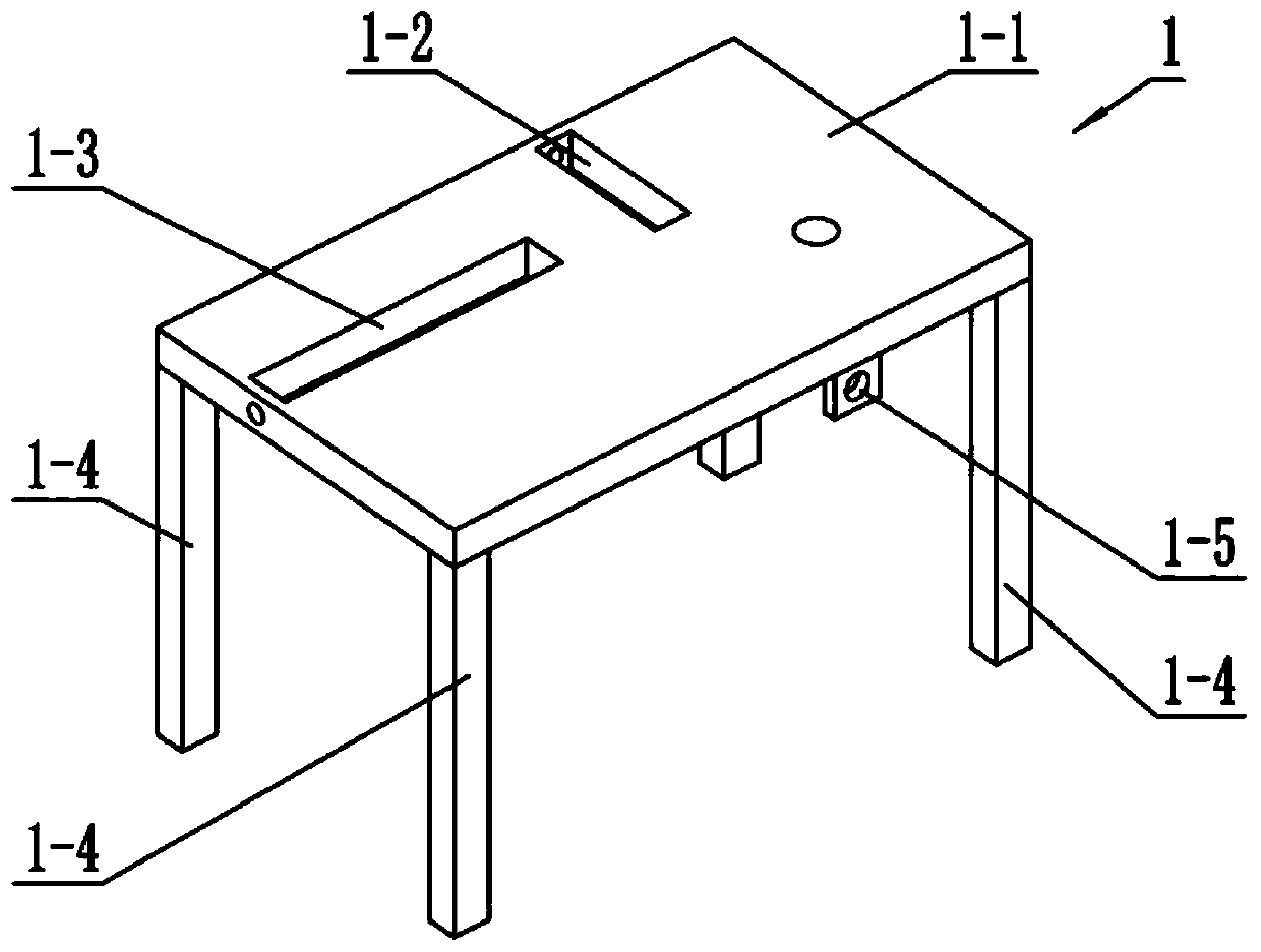
[0033] Such as Figure 1-11 As shown, the support frame 1 includes a main board 1-1, an auxiliary slideway 1-2, an end adjustment slideway 1-3, a leg 1-4 and a fixing plate 1-5, and the front and rear sides of the main board 1-1 are The direction is provided with auxiliary slideway 1-2, and the left and right direction of bearing mainboard 1-1 left end is provided with terminal adjustment slideway 1-3, and the four corners of bearing mainboard 1-1 lower end surface are all fixedly connected with supporting legs 1-4, fixed The board 1-5 is fixedly connected to the rear end of the lower end face of the main board 1-1;
specific Embodiment approach 3
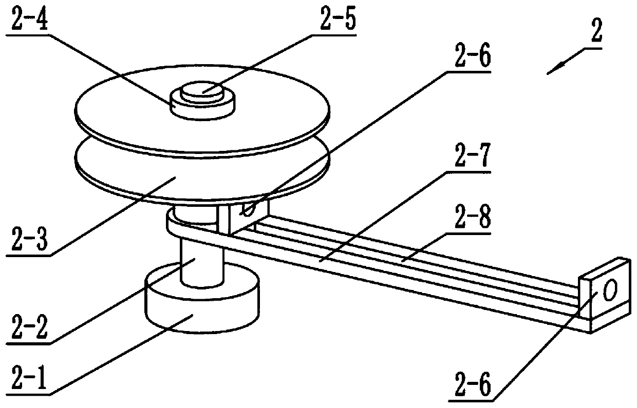
[0035] Such as Figure 1-11 As shown, the turret 2 includes a worm wheel 2-1, a rotating shaft 2-2, a support groove wheel 2-3, a limit nut I 2-4, a support shaft 2-5, a screw mounting plate 2-6, a folding Bending rotating plate 2-7 and bending chute 2-8, rotating shaft 2-2 is connected to the main board 1-1 in rotation, worm wheel 2-1 is fixedly connected to the lower end of rotating shaft 2-2, bending rotating plate 2-7 One end of the shaft is fixedly connected to the upper end of the rotating shaft 2-2, and the lower end of the supporting shaft 2-5 is fixedly connected to the bending rotating plate 2-7, the rotating shaft 2-2 is coaxial with the supporting shaft 2-5, and the groove wheel 2-5 is supported. 3 Rotationally connected to the support shaft 2-5, the limit nut Ⅰ2-4 is connected to the upper end of the support shaft 2-5 through threads, the limit nut Ⅰ2-4 presses against the support grooved wheel 2-3, and the screw mounting plate 2 -6 is provided with two, and two ...
PUM
 Abstract
Description
Claims
Application Information
 - R&D
- Intellectual Property
- Life Sciences
- Materials
- Tech Scout
- Unparalleled Data Quality
- Higher Quality Content
- 60% Fewer Hallucinations
Browse by: Latest US Patents, China's latest patents, Technical Efficacy Thesaurus, Application Domain, Technology Topic, Popular Technical Reports.
© 2025 PatSnap. All rights reserved.Legal|Privacy policy|Modern Slavery Act Transparency Statement|Sitemap|About US| Contact US: help@patsnap.com


