A mobile bypass cable laying and conveying equipment

A bypass cable, mobile technology, used in overhead line/cable equipment, transportation and packaging, transportation of filamentous materials, etc., can solve problems such as damage to bypass cables, safety accidents, and heavy workloads

Active Publication Date: 2021-09-14
徐州海伦哲特种车辆有限公司
View PDF4 Cites 0 Cited by
  • Summary
  • Abstract
  • Description
  • Claims
  • Application Information

AI Technical Summary

Problems solved by technology

[0004] The types of vehicles passing through different traffic intersections are different, and the load-carrying capacity of the bypass cable protection floor is also different. At the same time, the bypass cable protection floor is placed directly on the ground, similar to a speed bump. When vehicles pass, it is easy to cause the bypass cable protection floor to slide Or directly pushed away by the wheels, causing damage to the bypass cable in the bypass cable protection floor due to tension or failure of the bypass cable connection, resulting in a safety accident. For this reason, manual guards have to be used to guide the vehicle to slow down in advance , but for intersections with heavy traffic, it is still impossible to effectively avoid
The overhead laying of bypass cables for the entire line requires high investment and heavy workload, and there are potential safety hazards for laying on the ground. Up to now, there is no equipment for effectively laying bypass cables to solve the above problems

Method used


Image

  • A mobile bypass cable laying and conveying equipment
  • A mobile bypass cable laying and conveying equipment
  • A mobile bypass cable laying and conveying equipment

Examples


Embodiment 1

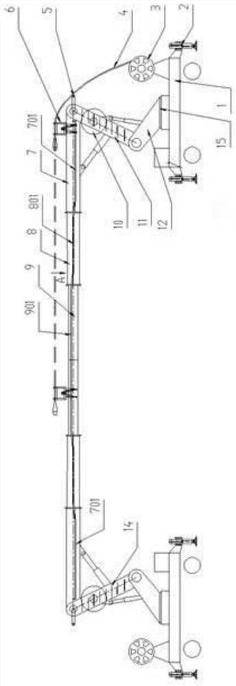
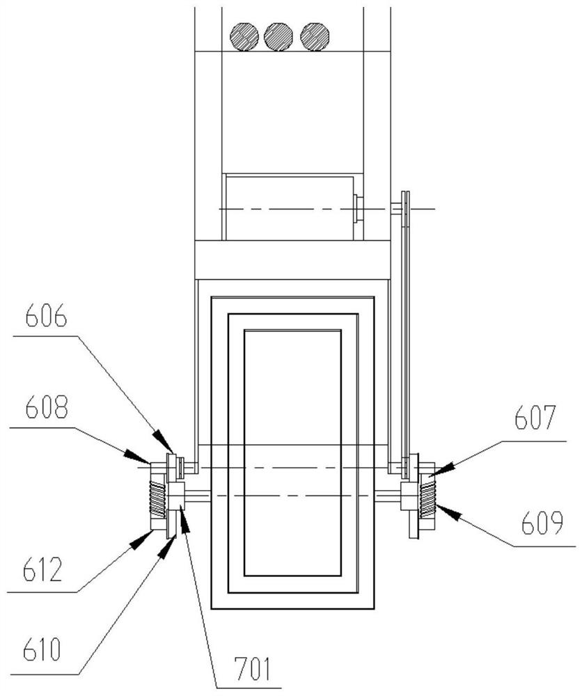
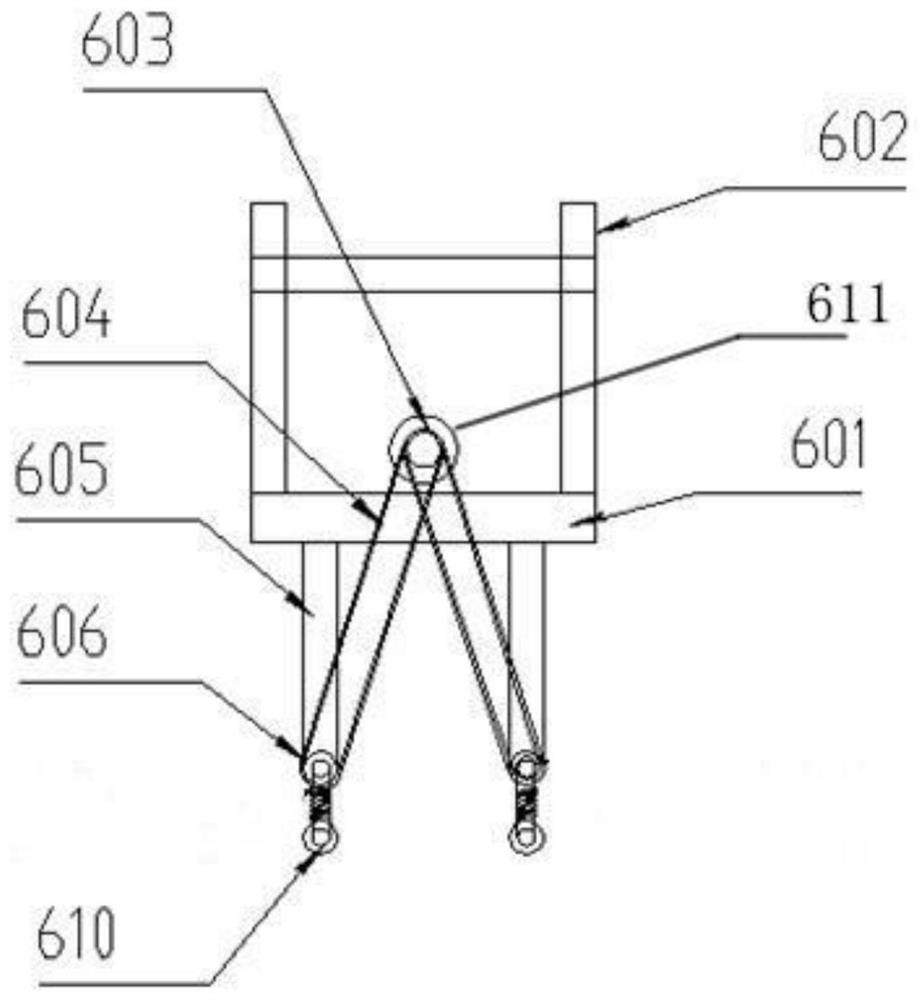
[0027] Embodiment one, as Figure 1 to Figure 5 As shown, a mobile bypass cable laying and conveying equipment includes two car bodies 1 symmetrically arranged on both sides of the road. The luffing mechanism is movably connected with a telescopic arm 7, and the telescopic arm 7 is provided with two telescopic joints, that is, a two-section telescopic joint 8 and a three-section telescopic joint 9, and the two sides of the telescopic arm 7 are fixed with a delivery track 701 by brackets, and two joints The two sides of the expansion joint 8 are fixed with a two-section conveying track 801 through brackets, and the two sides of the three-section expansion joint 9 are fixed with a three-section transmission track 901 through a bracket. Each bracket is fixed at the front end of each expansion joint. The distance between the conveying tracks on both sides of the telescopic joint is the same, and the one-section conveying track 701, the second-section conveying track 801 and the th...

Embodiment 2

[0035] Embodiment two, when the road is narrow, use a car body 1 to be located on the side of the road, all the other are the same as embodiment one, directly make the telescoping arm on the top of the car body 1 cross the road when in use, and put the bypass cable in the air Erection past opposite.

Embodiment 3

[0036] Embodiment 3, in order to facilitate the operation, a power system is separately provided on the car body 1 as required, and the power system provides kinetic energy for the car body 1, the jib luffing mechanism, the telescopic arm 7, the slewing mechanism 15 and the traction structure 6, and others are the same as those in the embodiment One is the same.


PUM


Abstract

The invention discloses a mobile bypass cable laying and conveying equipment, which comprises a vehicle body. A slewing mechanism is fixed in the middle of the slewing mechanism. A stretching mechanism capable of realizing vertical stretching and horizontal stretching is provided at the upper end of the swivel mechanism. There are conveying tracks on both sides of the extension end, on which a tractor is embedded and installed, and the tractor can drag the bypass cable along the conveying track and slide and walk on the horizontal extension end of the extension mechanism. The problem of laying across the road is solved by connecting a single or two mobile bypass cable conveying equipment on both sides of the road to form an overhead bypass cable conveying corridor, and transporting the bypass cable to the opposite side of the road through the tractor. Bypass operation The contradiction between bypass cables and road vehicles.

Description

technical field [0001] The invention relates to the field of bypass cable laying and conveying equipment, in particular to a mobile bypass cable laying and conveying equipment. Background technique [0002] As people's requirements for the reliability of power supply are getting higher and higher, power outages are basically not allowed in domestic electricity consumption. The power system generally adopts the method of bypass operation to realize the maintenance, replacement, and emergency repair of urban distribution network equipment. Bypass operation The biggest advantage is that it can realize the power outage operation of the faulty equipment in the distribution network without the user's power outage, so the application range is more and more extensive. [0003] The key equipment of the bypass operation is the bypass cable. The bypass cable replaces the original distribution network line. Therefore, the bypass cable needs to be laid first to carry out the bypass opera...

Claims


Application Information

Patent Timeline
Patent Type & Authority Patents(China)
IPC IPC(8): H02G1/04B65H51/32
CPCB65H51/32H02G1/04
Inventor 胡德敏袁玉柱狄纲要于百业王衡陈允柯郭维
Owner 徐州海伦哲特种车辆有限公司
Why Eureka
Try Eureka