
Impeller with adjustable impeller diameter for centrifugal pump

A technology for centrifugal pumps and impellers, which is applied to components, pumps, and pump controls of elastic fluid pumping devices, and can solve the problem of increasing water flow resistance, reducing the efficiency of centrifugal pumps and impeller speeds, and increasing mechanical losses in waterways and other problems to achieve the effect of increasing flow and head

Pending Publication Date: 2020-08-25
ZHEJIANG SCI-TECH UNIV
View PDF0 Cites 1 Cited by
  • Summary
  • Abstract
  • Description
  • Claims
  • Application Information

AI Technical Summary

Problems solved by technology

The diameter of the impeller of the centrifugal pump affects the flow rate of the centrifugal pump. The impeller diameter of the existing centrifugal pump is fixed, and the flow rate of the centrifugal pump is changed by adjusting the opening of the water outlet valve and the speed of the impeller, but the decrease in the opening of the water outlet valve will lead to an increase in water flow resistance. Large, increase the mechanical loss in the waterway, reduce the efficiency of the centrifugal pump and the speed of the impeller

Method used


Image

  • Impeller with adjustable impeller diameter for centrifugal pump
  • Impeller with adjustable impeller diameter for centrifugal pump
  • Impeller with adjustable impeller diameter for centrifugal pump

Examples


Embodiment Construction

[0024] In order to make the purpose, technical solution and advantages of the present invention clearer, the present invention will be further described below with reference to the accompanying drawings.

[0025] In the description of the present invention, it should be understood that the terms "upper", "lower", "front", "rear", etc. indicating orientation or positional relationship are based on the orientation or positional relationship shown in the drawings, and are only for the purpose of The present invention is briefly described and described for convenience, but does not indicate or imply a specific orientation that the indicated devices or elements must have, and therefore, should not be construed as limiting the present invention.

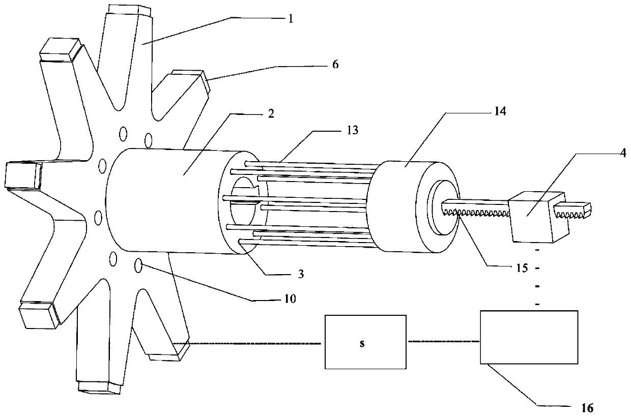
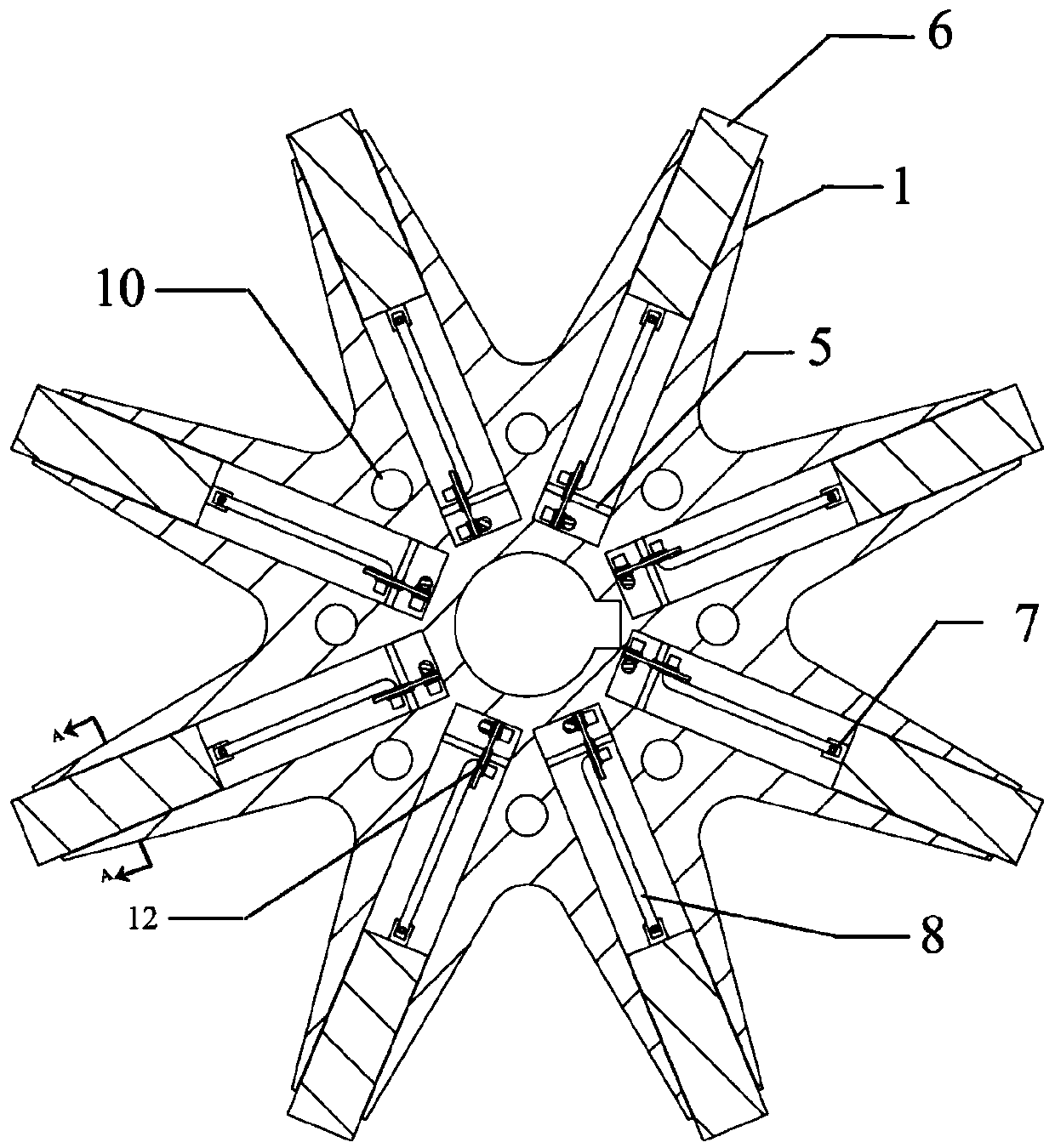
[0026] Such as figure 1 As shown, the specific implementation device includes a fixed impeller 1, an impeller central cavity 2, a strip groove 3, a ring 14 and a moving groove 17; the impeller central cavity 2 is coaxially fixed at the cen...


PUM


Abstract

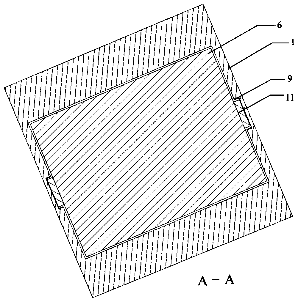
The invention discloses an impeller with an adjustable impeller diameter for a centrifugal pump. The impeller comprises a fixing impeller, an impeller center cavity, strip-shaped grooves, a circular ring and a movable groove body, wherein rotating discs are mounted at the joint of the inner end of a mounting cavity and an axial channel, the rotating discs are hinged to the mounting cavity, connecting pull rods are located in the strip-shaped grooves around the outer wall of the impeller center cavity, extend out of the strip-shaped grooves outwards in the radial direction and then are fixedlyconnected to the inner ring of the circular ring, and the inner ends of the connecting pull rods extend out of the strip-shaped grooves, are bent to the axial channel, and extend into the mounting cavity to be hinged to the rotating discs; movable rods are hinged between movable blades and the rotating discs; electromagnetic sensors are mounted in the mounting cavity of the movable blades, the circular ring can circumferentially rotate and movably mounted the movable groove body in a sleeving mode, the movable groove body is fixedly connected with a movable rod, the movable rod is arranged inthe axial direction parallel to the fixing impeller, and the movable rod is connected with a movement driver. According to the impeller with the adjustable impeller diameter for the centrifugal pump,the impeller diameter of the centrifugal pump can be adjusted in real time and changed, the flow and the lift of the centrifugal pump are increased on the premise that the mechanical loss of the centrifugal pump is not increased, and the impeller can be used for experimental tests and the like.

Description

technical field [0001] The invention relates to an impeller structure of a pump body, in particular to an impeller for a centrifugal pump with an adjustable impeller diameter. Background technique [0002] The function of the centrifugal pump is a device that converts the kinetic energy of the motor into the kinetic energy of the conveying fluid. It uses the centrifugal force generated by the rotation of the impeller to separate the water, so that it is thrown to the edge of the impeller and flows through the volute casing into the pressure of the centrifugal pump. pipeline. The diameter of the impeller of the centrifugal pump affects the flow rate of the centrifugal pump. The impeller diameter of the existing centrifugal pump is fixed, and the flow rate of the centrifugal pump is changed by adjusting the opening of the water outlet valve and the speed of the impeller, but the decrease in the opening of the water outlet valve will lead to an increase in water flow resistance...

Claims


Application Information

Patent Timeline
Patent Type & Authority Applications(China)
IPC IPC(8): F04D29/22F04D29/02F04D15/00
CPCF04D15/00F04D29/026F04D29/2222F04D29/2227
Inventor 崔宝玲王振陈德胜韩啸天
Owner ZHEJIANG SCI-TECH UNIV
Learn More