
Pneumatic turbine type air-jetting sludge stirring device

A technology of pneumatic turbine and turbofan, which is applied to components of pumping devices for elastic fluids, radial flow pumps, machines/engines, etc., can solve the problems of reduced sludge discharge efficiency and impact on construction efficiency, and achieve high efficiency Effects of sludge discharge, improvement of construction efficiency, and improvement of discharge efficiency

Pending Publication Date: 2020-08-25
THE 5TH ENG MBEC +2
View PDF0 Cites 0 Cited by
  • Summary
  • Abstract
  • Description
  • Claims
  • Application Information

AI Technical Summary

Problems solved by technology

[0005] Aiming at the defects existing in the prior art, the object of the present invention is to provide a pneumatic turbine type jet mud mixing device, which can effectively solve the problem that the air lift reverse circulation sludge discharge device in the prior art will cause A bowl-shaped concave surface will be formed, and the sludge discharge efficiency will be reduced, which will affect the construction efficiency.

Method used


Image

  • Pneumatic turbine type air-jetting sludge stirring device
  • Pneumatic turbine type air-jetting sludge stirring device
  • Pneumatic turbine type air-jetting sludge stirring device

Examples


Embodiment Construction

[0046] In order to make the purposes, technical solutions and advantages of the embodiments of the present application clearer, the technical solutions in the embodiments of the present application will be clearly and completely described below in conjunction with the drawings in the embodiments of the present application. Obviously, the described embodiments It is a part of the embodiments of this application, but not all of them. Based on the embodiments in the present application, all other embodiments obtained by persons of ordinary skill in the art without making creative efforts belong to the protection scope of the present application. Embodiments of the present invention will be described in further detail below in conjunction with the accompanying drawings.

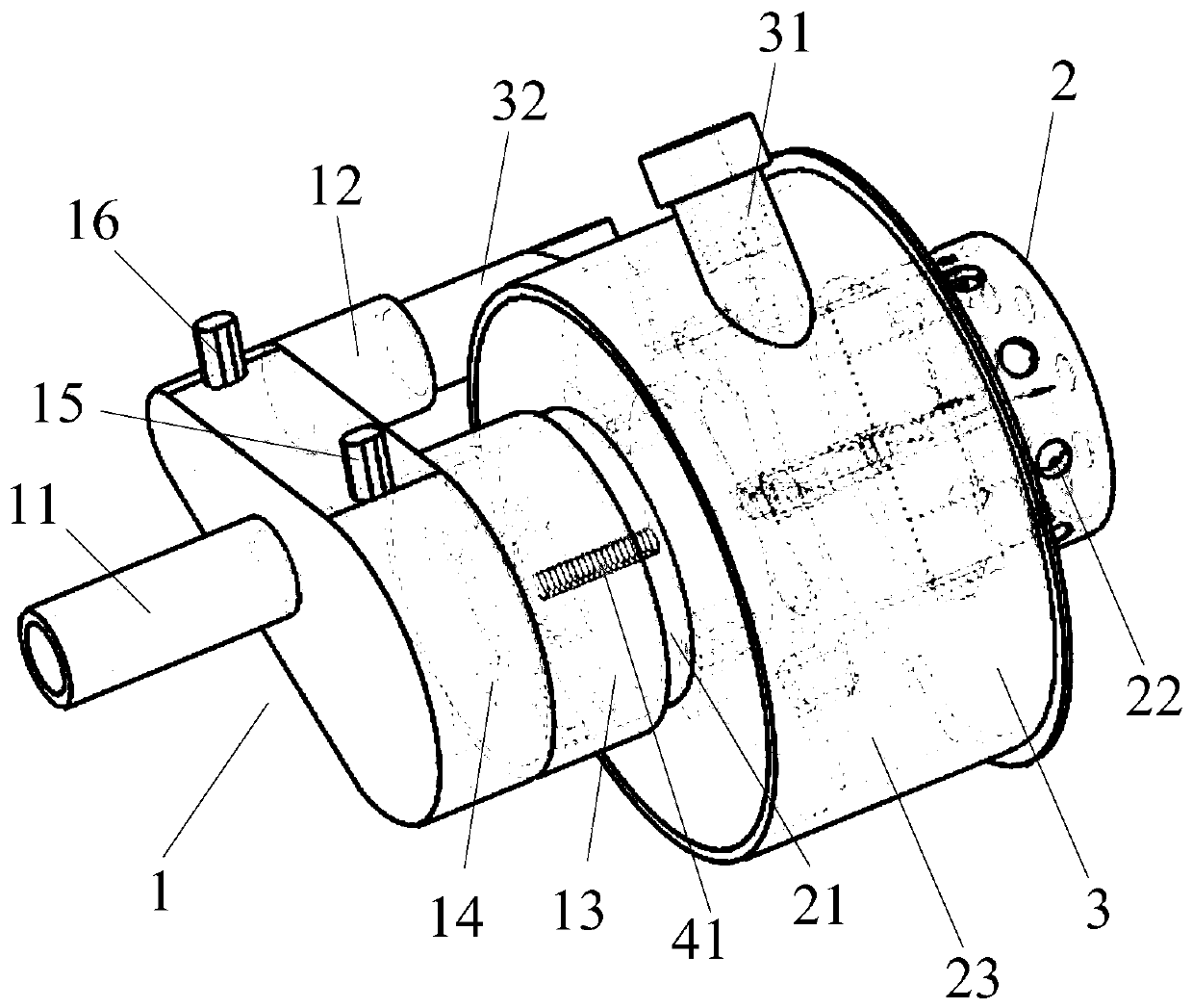
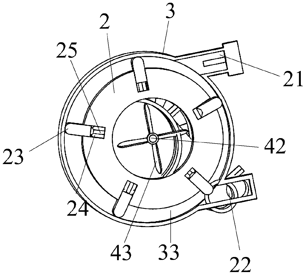
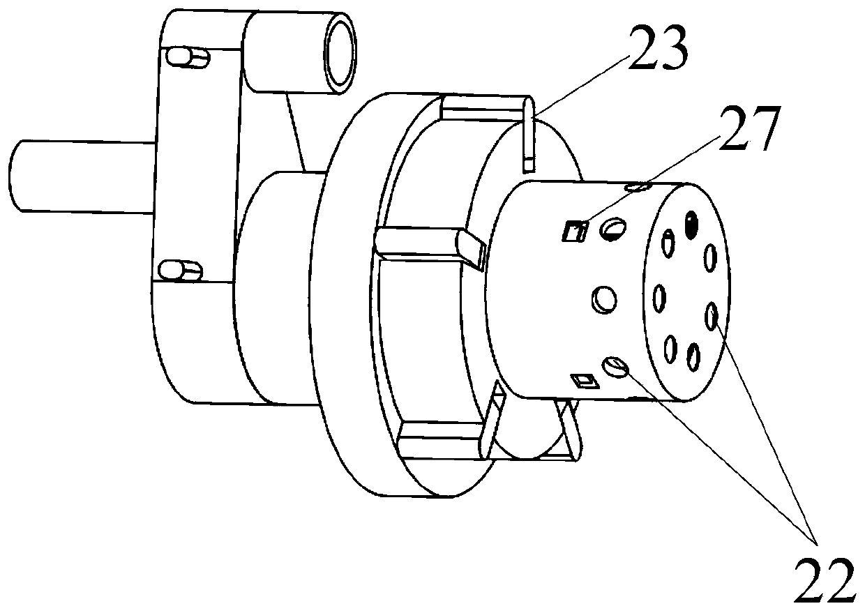
[0047] figure 1 It is a schematic structural view of a pneumatic turbine type jet mud mixing device in an embodiment of the present invention; figure 2 It is an axial sectional view of the pneumatic turbine ty...


PUM


Abstract

The invention relates to the technical field of piling drilling construction, in particular to a pneumatic turbine type air-jetting sludge stirring device. The device comprises an air distributing cabin, a rotor and a stator, wherein the air distributing cabin comprises a main air inlet, a bypass power air outlet and a central main air outlet which communicate with each other; one end of the rotoris provided with a rotor air inlet rotatably connected with the central main air outlet, air outlets are formed in the side wall of the other end of the rotor at intervals, and blades are arranged inthe middle of the rotor at intervals in the circumferential direction; and the stator is arranged in the middle of the rotor in a sleeving mode, the blades are located in an accommodating space formed by the stator and the rotor, the accommodating space is provided with a driving air outlet and a driving air inlet communicating with the bypass power air outlet, and high pressure air introduced from the bypass power air outlet can push the blades to make the rotor rotate relative to the stator, and then is discharged from the driving air outlet. The device can effectively solve the problems that in the prior art, when an air-lifting reverse circulation sludge discharging device is used, a bowl-opening-shaped concave surface is formed around an air discharging hole, the sludge discharging efficiency is low, and construction efficiency is affected.

Description

technical field [0001] The invention relates to the technical field of piling and drilling construction, in particular to a pneumatic turbine-type blast mud mixing device. Background technique [0002] During the construction of the bridge foundation, the silt in the piling process needs to be discharged above the water level through air lift reverse circulation. [0003] The working principle of gas lift reverse circulation drilling is similar to the working principle of air lift pumping of air compressor, that is, the compressed air passes through the double-wall air faucet, and passes through the double-wall active drill pipe, the inner pipe and the outer pipe of the double-wall drill pipe. The annular gap is sprayed into the inner tube from the mixer, forming countless small bubble channels. The bubbles rise rapidly along the inner tube while expanding at the same time, and the pressure decreases, thereby generating gas lift. [0004] However, in the existing gas-lift r...

Claims


Application Information

Patent Timeline
Patent Type & Authority Applications(China)
IPC IPC(8): F04D17/16F04D29/02F04D29/30F04D29/42F04D29/46
CPCF04D17/16F04D29/023F04D29/30F04D29/4226F04D29/462
Inventor 王梓宇王鹏邹欢邓永锋王翔李璘琳江海明陈晓剑徐进
Owner THE 5TH ENG MBEC
Learn More