
Foam filling type vane rear edge bonding corner and preparation method

A technology of blade trailing edge and foam filling, which is applied to chemical instruments and methods, mechanical equipment, wind turbines that are consistent with the wind direction, etc. Avoid wrinkling or slumping, reduce mold time, and optimize the effect of structure

Pending Publication Date: 2020-08-25
国能联合动力技术(保定)有限公司
View PDF0 Cites 2 Cited by
  • Summary
  • Abstract
  • Description
  • Claims
  • Application Information

AI Technical Summary

Problems solved by technology

If the female mold is used, the space is too small to reach in, and the bonding corners are easy to wrinkle or collapse, which requires rework. If the male mold is used, there is still the problem that the mold is not easy to take out.

Method used


Image

  • Foam filling type vane rear edge bonding corner and preparation method

Examples


Embodiment Construction

[0016] In order to better understand the purpose, structure and function of the present invention, a foam-filled blade trailing edge bonding angle and a preparation method of the present invention will be further described in detail below in conjunction with the accompanying drawings.

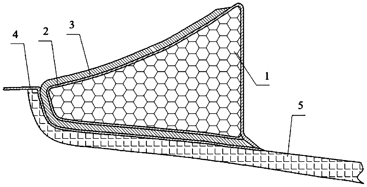
[0017] Such as figure 1 As shown, it shows a foam-filled blade trailing edge bonding corner of the present invention, including foam, cladding layer 2, trailing edge bonding corner 3, and positioning layer 4. The air between the positioning layer 4, the FRP adhesive layer 3 and the cladding layer 2 is extracted by vacuuming auxiliary materials, so that the positioning layer 4, the FRP bonding layer 3 and the cladding layer 2 are flat and attached to the outside of the foam.

[0018] Further, it is preferable that the foam adopts polyurethane foam material to fill the bonding angle of the trailing edge of the blade in the form of foaming to fill up a certain cavity. In the present invention, the...


PUM


Abstract

The invention discloses a foam filling type vane rear edge bonding corner and a preparation method. The foam filling type vane rear edge bonding corner comprises foam, a cladding layer, a glass fiberreinforced plastic bonding layer and a locating layer. The foam is matched with the shape of an inner chamber in the area of the vane rear edge bonding corner and used for filling the vane rear edge bonding corner. The cladding layer is arranged outside the foam in a sleeving manner. The glass fiber reinforced plastic bonding layer is arranged outside the cladding layer and the foam in a sleevingmanner. The locating layer is arranged between the glass fiber reinforced plastic bonding layer and a SS face shell. Air among the locating layer, the glass fiber reinforced plastic bonding layer andthe cladding layer is extracted through a vacuum extraction auxiliary material so that the locating layer, the glass fiber reinforced plastic bonding layer and the cladding layer can be flatly and closely attached to the outside of the foam. The foam filling type vane rear edge bonding corner is optimal in structure, convenient to form, good in shape follow-up performance and low in cost; a foam filling method is adopted for producing the rear edge bonding corner, and a bonding corner mold is not needed; a glass fiber fabric is easy to lay, adjust and closely attach and easy and convenient tooperate; the bonding corner can be located precisely; the resin excessiveness phenomenon occurring between a mold closing platform and the bonding corner is avoided; the problem that the bonding corner is crinkled or collapsed is avoided; and the repair cost is lowered.

Description

technical field [0001] The invention relates to the technical field of wind power generator manufacturing equipment, in particular to a foam-filled trailing edge bonding angle of a blade and a preparation method thereof. Background technique [0002] When bonding the trailing edge of the wind turbine blade shell, some positions need to prepare the trailing edge bonding corner first, and then scrape the adhesive on the bonding corner to complete the mold clamping bonding. There are two ways to make the trailing edge bonding corner, one is hand lay-up before mold closing, and the other is pouring molding with the shell as a whole. [0003] The inner cavity of the trailing edge of existing wind power blades is very irregular and varies greatly. The radian of some positions is relatively large, and the section of the inner cavity is close to the "Ω" shape, that is, a structure with a large inner cavity but a small opening is formed. If a positive mold is used to make it, the m...

Claims


Application Information

Patent Timeline
Patent Type & Authority Applications(China)
IPC IPC(8): F03D1/06B29C70/44B32B1/00B32B27/06B32B27/12B32B17/02B32B17/06B32B37/02B32B38/18B32B33/00
CPCF03D1/0675B29C70/443B32B1/00B32B27/06B32B27/12B32B5/08B32B37/02B32B33/00B32B38/1841B29L2031/085B32B2262/101B32B2457/00Y02E10/72
Inventor 刘梅刘广李江波赵亚男杨潺姜宏业冀亚涛
Owner 国能联合动力技术(保定)有限公司
Learn More