
Oily sludge reduction comprehensive experiment device

An experimental device and sludge reduction technology, applied in sludge treatment, electrochemical sludge treatment, water/sludge/sewage treatment, etc., can solve the inconvenient setting of ultrasonic composite action frequency, the inability to quantitatively investigate adsorption-assisted dewatering, The problem of single electroosmosis electric field setting can achieve the effect of improving dehydration efficiency, improving dehydration effect and efficiency, and reducing energy consumption

Pending Publication Date: 2020-08-25
哈工大机电工程(嘉善)研究院
View PDF0 Cites 1 Cited by
  • Summary
  • Abstract
  • Description
  • Claims
  • Application Information

AI Technical Summary

Problems solved by technology

[0006] The purpose of the present invention is to provide a kind of oil-contained oil-contaminated water for the problems existing in the prior art, such as inconvenient adjustment of pressure, single setting of electroosmotic electric field, inconvenient setting of frequency of ultrasonic composite action, uneven effect of sound waves, and incapable of quantitative investigation of adsorption-assisted dehydration. Comprehensive experimental device for mud reduction

Method used


Image

  • Oily sludge reduction comprehensive experiment device
  • Oily sludge reduction comprehensive experiment device
  • Oily sludge reduction comprehensive experiment device

Examples


specific Embodiment approach 3

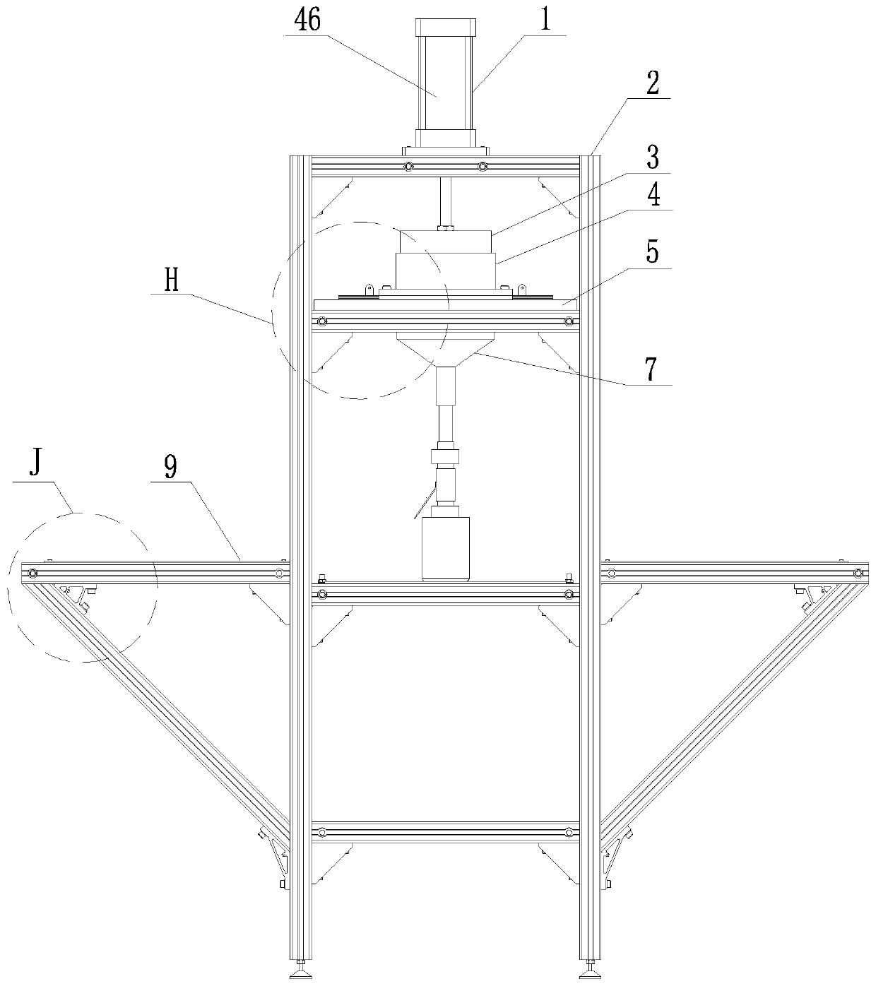
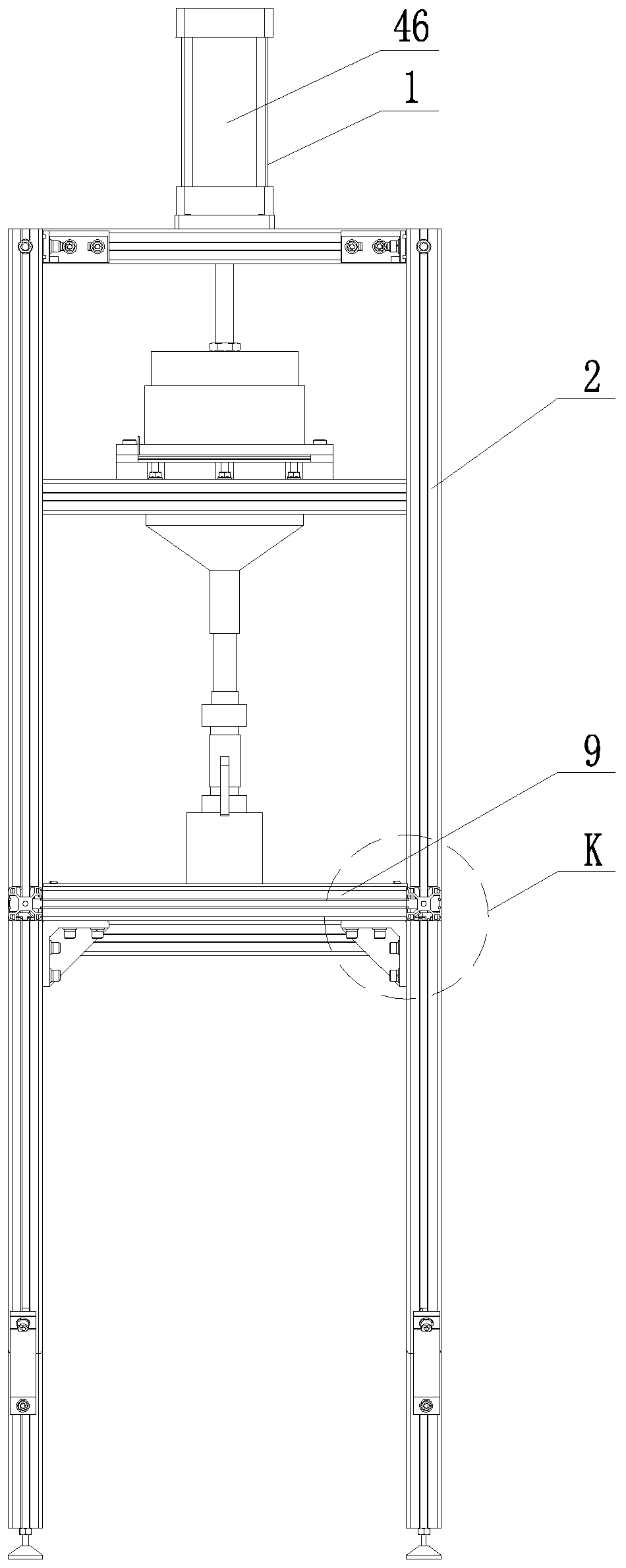
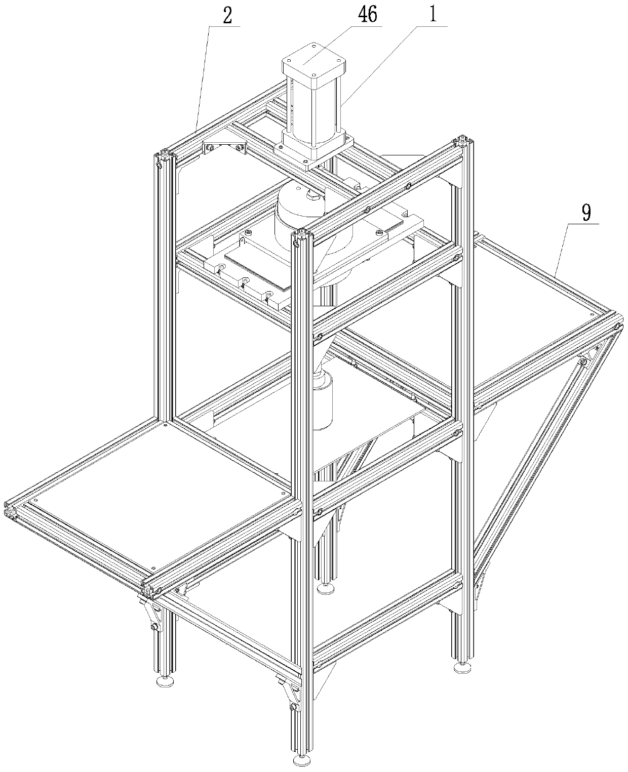
[0033] Specific implementation mode three: as figure 1 , Figure 5 , Image 6 , Figure 12 , Figure 13 , Figure 15 As shown, the comprehensive experimental device for oily sludge reduction described in Embodiment 1, the integrated piston 3 includes a joint nut 32, a piston cylinder cover 33, an insulating washer 35, an anode joint 36, a vibrator mounting plate 38, Anode plate 39, dehydration insulating sleeve 40, dehydration steel drum 41 and 2-4 ultrasonic vibrators 34;

[0034] The dehydration steel drum 41 is a cavity structure with upper and lower ends open. The dehydration insulating sleeve 40 is arranged in the dehydration steel drum 41 and bonded to the inner wall of the dehydration steel drum 41. The piston rod of the cylinder 46 is connected to the piston cylinder outer cover through the joint nut 32. The top of 33 is fastened and connected (the piston rod of cylinder 46 is provided with external thread, and the top of piston cylinder housing 33 is provided wit...


PUM


Abstract

The invention discloses an oily sludge reduction comprehensive experiment device and belongs to the technical field of oily sludge treatment and aims to solve the problems of inconvenient pressure adjustment, single electroosmosis electric field arrangement mode, inconvenience in setting ultrasonic composite action frequency, uneven sound wave, action and failure to quantitatively investigate adsorption-assisted dehydration in the prior art. An air cylinder of a pneumatic device is fixed at the top of a bracket; a piston rod of the air cylinder of the pneumatic device is vertically arranged downwards and connected with the top of a piston cylinder outer cover of an integrated piston; a cathode dehydration material layer is arranged at the lower end of the integrated piston and fixedly connected with the bracket; the lower end of the cathode dehydration material layer is connected with the upper end of a water collection and vacuum suction filtration device in a sealed mode; and experiment platforms are fixed to the left side and the right side of the bracket respectively. In a whole experiment process, different electric fields, pressures, ultrasonic waves and vacuum suction filtration modes are adopted to perform comprehensive dehydration on oily sludge, so that optimal process conditions are further explored, energy consumption is reduced, and a dehydration effect and efficiency are improved.

Description

technical field [0001] The invention belongs to the technical field of oily sludge treatment, and in particular relates to a comprehensive experimental device for reducing the amount of oily sludge. Background technique [0002] Oily sludge is one of the solid wastes produced in the process of petroleum exploration, mining, refining, processing, storage, transportation, etc. According to the way of generating oily sludge, it can be divided into oilfield sludge, refining sludge and storage and transportation sludge. In addition, some other industries, such as steel, transportation and food industries, etc. will also produce a certain amount of oily sludge. Relevant information shows that the annual production of oily sludge in my country has exceeded 5 million tons, and the production volume is increasing year by year. The composition of oily sludge is complex, containing a large amount of aged crude oil, wax, asphaltene, and benzene series, phenols, onions, heavy metals an...

Claims


Application Information

Patent Timeline
Patent Type & Authority Applications(China)
IPC IPC(8): C02F11/00C02F11/122C02F11/15
CPCC02F11/122C02F11/15C02F11/006C02F2303/06
Inventor 万德胜焦映厚谢品友曲秀全
Owner 哈工大机电工程(嘉善)研究院
Learn More