
Conveying device used for printed matter cold-foil printing

A conveying device and printing technology, applied in general parts of printing machinery, printing, printing machines, etc., can solve the problems of rubber layer wear, reduce friction effect, etc., and achieve the effect of firm fixation and simple and convenient operation.

Pending Publication Date: 2020-08-25
GUIZHOU XINIUWANG PRINTING
View PDF0 Cites 2 Cited by
  • Summary
  • Abstract
  • Description
  • Claims
  • Application Information

AI Technical Summary

Problems solved by technology

[0002] In the work of the rotary roller in the cold press printing machine in the prior art, the rotary roller in some machines needs special treatment, and the rubber layer needs to be wrapped on the rotary roller to increase the friction between the rotary roller and the conveyed belt-shaped product , to ensure stable and efficient conveying work. If the rubber layer is directly wrapped on the outer wall of the roller, it cannot meet the regular replacement and maintenance work. Long-term contact friction may cause wear of the rubber layer and reduce the friction effect

Method used


Image

  • Conveying device used for printed matter cold-foil printing
  • Conveying device used for printed matter cold-foil printing
  • Conveying device used for printed matter cold-foil printing

Examples


Embodiment Construction

[0019] The following will clearly and completely describe the technical solutions in the embodiments of the present invention with reference to the accompanying drawings in the embodiments of the present invention. Obviously, the described embodiments are only some, not all, embodiments of the present invention. Based on the technical solutions in the present invention, all other embodiments obtained by persons of ordinary skill in the art without making creative efforts belong to the protection scope of the present invention.

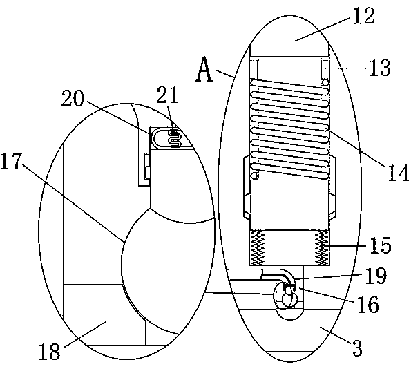
[0020] see Figure 1 to Figure 4 , the present invention provides a technical solution: a transmission device for cold stamping printing, including a rotary roller 1, the outer part of the rotary roller 1 is covered with a rubber tube 2, and the middle ring of the rotary roller 1 is provided with a number of evenly distributed collecting and distributing lumens-3 and the collecting and distributing lumen two 4, the rotating roller 1 on the one side of ...


PUM


Abstract

The invention relates to the technical field of cold-foil printing, in particular to a conveying device used for printed matter cold-foil printing. The conveying device used for printed matter cold-foil printing comprises a rotating roller, a rubber cylinder is sleeved outside the rotating roller, a plurality of uniformly distributed collecting and distributing pipe cavities I and collecting and distributing pipe cavities II are annularly arranged in the rotating roller, an annular pipe cavity I is formed in a position, on one side of the collecting and distributing pipe cavities I, on the rotating roller, and an annular pipe cavity II is formed in the position, on one side of collecting and distributing pipe cavities II, on the rotating roller. By means of the structural design of the conveying device used for printed matter cold-foil printing, time pressure of telescopic columns on the rubber cylinder is achieved, mutual positioning connection is achieved through friction force, therotating roller rotates to stably drive the rubber cylinder, and if the rubber cylinder needs to be taken down, a pressure rod needs to be manually pulled in a reciprocating mode, so that controllinga sliding column is realized, then a plurality of telescopic columns retract into the rotating roller, the synchronous fixing state of the rotating roller and the rubber cylinder is broken, the rubbercylinder is pulled down from the rotating roller, and the operation is easy, convenient and fast.

Description

technical field [0001] The invention relates to the technical field of cold stamping printing, in particular to a conveying device for cold stamping printing of printed matter. Background technique [0002] In the work of the rotary roller in the cold press printing machine in the prior art, the rotary roller in some machines needs special treatment, and the rubber layer needs to be wrapped on the rotary roller to increase the friction between the rotary roller and the conveyed belt-shaped product , to ensure stable and efficient conveying work. If the rubber layer is directly wrapped on the outer wall of the roller, it cannot meet the regular replacement and maintenance work. Long-term contact friction may cause wear of the rubber layer and reduce the friction effect. [0003] If a rotary roller can be invented, the replacement of the rubber layer can be realized conveniently and quickly, and the problem can be solved. For this reason, we provide a transfer device for cold ...

Claims


Application Information

Patent Timeline
Patent Type & Authority Applications(China)
IPC IPC(8): B65H29/20B41F21/00
CPCB41F21/00B65H29/20
Inventor 龚立朋聂文豪陈其梅冉益全李正远
Owner GUIZHOU XINIUWANG PRINTING
Learn More