
Clamping device for glass processing machinery

The technology of processing machinery and clamping device is applied in the field of clamping devices for glass processing machinery, which can solve the problems of no adjustment function and poor use flexibility, and achieve the effect of avoiding poor device balance, flexible use and convenient clamping.

Active Publication Date: 2022-04-08
上海神网辐射防护器材有限公司
View PDF0 Cites 1 Cited by
  • Summary
  • Abstract
  • Description
  • Claims
  • Application Information

AI Technical Summary

Problems solved by technology

[0002] In the process of glass processing, glass needs to be processed in multiple processes, so it is necessary to transfer glass from one station to another. Now the clamping device used for glass transfer usually uses suction cups to directly contact vacuum glass for adsorption. As long as the seal between the rubber suction cup and the vacuum glass can be guaranteed, the normal use of the suction cup can be guaranteed. However, the suction cup of the adsorption fixture currently used is usually fixed in position, has no adjustment function, and has poor flexibility in use. Therefore, a clamp for glass processing machinery is introduced. support device to solve the above problems

Method used


Image

  • Clamping device for glass processing machinery
  • Clamping device for glass processing machinery
  • Clamping device for glass processing machinery

Examples


Embodiment Construction

[0024] The following will clearly and completely describe the technical solutions in the embodiments of the present invention with reference to the accompanying drawings in the embodiments of the present invention. Obviously, the described embodiments are only some, not all, embodiments of the present invention. Based on the embodiments of the present invention, all other embodiments obtained by persons of ordinary skill in the art without making creative efforts belong to the protection scope of the present invention.

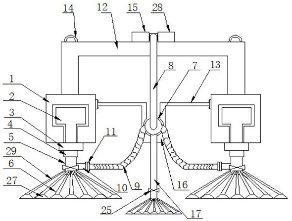
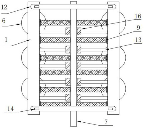
[0025] The present invention provides such as Figure 1-5 The shown clamping device for glass processing machinery includes two symmetrical steel channels 1, and the inside of the two steel channels 1 are respectively provided with T-shaped slideways, and several T-shaped slideways are slidingly connected to each other. T-shaped slider 2, the lower end of each T-shaped slider 2 is sleeved with a partition steel block 3 located below the steel channel 1, and th...


PUM


Abstract

The invention discloses a clamping device for glass processing machinery, which comprises two symmetrical steel grooves, a plurality of T-shaped sliders are slidably connected to the T-shaped slideway, and the lower end of each T-shaped slider is sleeved A clapboard steel block located below the steel channel is connected, and a lock nut screwed to the T-shaped slider is provided under the clapboard steel block, and a lock nut located under the lock nut is welded under the T-shaped slide block. The third suction pipe, the bottom of the third suction pipe is connected with a suction cup, the second suction pipe is arranged between the two steel channels, and a suction nozzle is installed on one side of the third suction pipe, The clamping device for glass processing machinery can adjust the installation position of the suction cup according to the size of the glass, and is flexible to use. The invention uses the T-shaped slider to slide in the steel groove by unscrewing the lock nut on the T-shaped slider. The position of the suction cup can be adjusted according to the size of the glass. After the position of the suction cup is adjusted, use the lock nut to lock the T-shaped slider.

Description

technical field [0001] The invention belongs to the technical field of glass processing and transfer fixtures, and in particular relates to a clamping device for glass processing machinery. Background technique [0002] In the process of glass processing, glass needs to be processed in multiple processes, so it is necessary to transfer glass from one station to another. Now the clamping device used for glass transfer usually uses suction cups to directly contact vacuum glass for adsorption. As long as the seal between the rubber suction cup and the vacuum glass can be guaranteed, the normal use of the suction cup can be guaranteed. However, the suction cup of the adsorption fixture currently used is usually fixed in position, has no adjustment function, and has poor flexibility in use. Therefore, a clamp for glass processing machinery is introduced. holding device to solve the above problems. Contents of the invention [0003] The object of the present invention is to pro...

Claims


Application Information

Patent Timeline
Patent Type & Authority Patents(China)
IPC IPC(8): B28D7/04B28D7/00
CPCB28D7/046B28D7/005B28D7/00
Inventor 闫凤杰李晓静
Owner 上海神网辐射防护器材有限公司
Learn More