Guiding blade mold and design method for contraction thereof
A guide vane and mold shrinkage technology, which is applied in the field of precision casting, can solve the problems of prolonged delivery period, inability to open the mold, and out-of-tolerance blade throat area, and achieve the goal of solving mold opening interference, promoting engineering application, and improving design technology Effect
- Summary
- Abstract
- Description
- Claims
- Application Information
AI Technical Summary
Problems solved by technology
Method used
Image
Examples
Embodiment 1
[0053] A slender five-joint equiaxed crystal turbine guide vane of an engine blade:
[0054] Step 1, set parameters
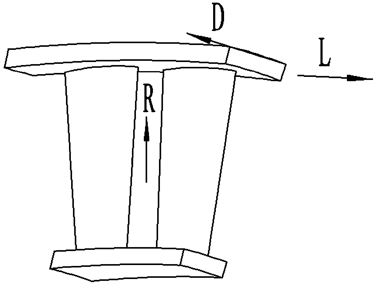
[0055] The length of the blade body is A=225mm; the length direction of the blade is the R direction, which coincides with the coordinate axis Z axis, and the shrinkage rate is ψ1=2.4%;
[0056] The chord length direction of the upper and lower edge plates is the L direction, which coincides with the X axis of the coordinate axis, and the shrinkage rate is ψ2=1.8%;
[0057] The width direction of the upper and lower edge plates is the D direction, which coincides with the coordinate axis Y axis, and the shrinkage rate is ψ3=1.8%.
[0058] Step 2, mold shrinkage setting method
[0059] Taking the origin of the blade engine as the center of the circle, the blade is enlarged as a whole according to the shrinkage rate of 1.8%. The shrinkage rate given in the direction of the blade body is 0.6% smaller than the actual shrinkage rate, and the length of the blade bo...
Embodiment 2
[0062] A single-connected equiaxed crystal turbine guide vane with short blade body and large edge plate in an engine:
[0063] Step 1, set parameters
[0064] The blade body length is A=110mm;
[0065] The length direction of the blade is the R direction, which coincides with the coordinate axis Z axis, and the shrinkage rate is ψ1=1.8%;
[0066] The chord length direction of the upper and lower edge plates is the L direction, which coincides with the X axis of the coordinate axis, and the shrinkage rate is ψ2=2.2%;
[0067] The width direction of the upper and lower edge plates is the D direction, which coincides with the coordinate axis Y axis, and the shrinkage rate is ψ3=2.2%.
[0068] Step 2, mold shrinkage setting method
[0069] Taking the origin of the blade engine as the center of the circle, the blade is enlarged as a whole according to the shrinkage rate of 2.2%. The shrinkage rate given in the direction of the blade body is 0.4% larger than the actual shrinkage...
Embodiment 3
[0071] A single directionally solidified turbine guide vane with the same size as the airfoil and edge plate of an engine:
[0072] Step 1, given parameters
[0073] The blade body length is A=180mm;
[0074] The length direction of the blade is the R direction, which coincides with the coordinate axis Z axis, and the shrinkage rate is ψ1=1.6%;
[0075] The chord length direction of the upper and lower edge plates is the L direction, which coincides with the X axis of the coordinate axis, and the shrinkage rate is ψ2=2.1%;
[0076] The width direction of the upper and lower edge plates is the D direction, which coincides with the coordinate axis Y axis, and the shrinkage rate is ψ3=2.1%.
[0077] Step 2, mold shrinkage setting method
[0078] Taking the origin of the blade engine as the center of the circle, the blade is enlarged as a whole according to the shrinkage rate of 2.1%. The shrinkage rate given in the direction of the blade body is 0.5% larger than the actual shr...
PUM
 Abstract
Description
Claims
Application Information
 - R&D Engineer
- R&D Manager
- IP Professional
- Industry Leading Data Capabilities
- Powerful AI technology
- Patent DNA Extraction
Browse by: Latest US Patents, China's latest patents, Technical Efficacy Thesaurus, Application Domain, Technology Topic, Popular Technical Reports.
© 2024 PatSnap. All rights reserved.Legal|Privacy policy|Modern Slavery Act Transparency Statement|Sitemap|About US| Contact US: help@patsnap.com


