A steel ring presser foot chamfering all-in-one machine

An all-in-one machine and steel ring technology, applied in the field of steel ring manufacturing, can solve problems such as low efficiency, injury, cutting hands, etc., achieve the effects of reducing labor intensity, realizing processing automation, and improving safety and work efficiency

Active Publication Date: 2021-09-07
NINGBO JINSHIHONG MACHINERY EQUIP CO LTD
View PDF5 Cites 0 Cited by
  • Summary
  • Abstract
  • Description
  • Claims
  • Application Information

AI Technical Summary

Problems solved by technology

[0003] At present, in order to better fit the pot lid, the manufacturing process of the steel ring is relatively complicated. The process usually includes ringing, welding, edge pulling, curling and chamfering. The curling process is completed in a special curling device. After the edge is completed, its shape is as shown in the instruction manual. figure 1 As shown, at this time, the lower end of the steel ring is only bent, and the worker needs to take it out and put it into a special presser foot device and chamfering device, so that the final product is as shown in the manual. figure 2 As shown, but because the steel ring is relatively thin and sharp, the hand is often cut when taking it out manually, causing injury, and the presser foot and chamfering are divided into two processes, the efficiency is relatively low, and the output needs to be improved

Method used


Image

  • A steel ring presser foot chamfering all-in-one machine
  • A steel ring presser foot chamfering all-in-one machine
  • A steel ring presser foot chamfering all-in-one machine

Examples


Embodiment 1

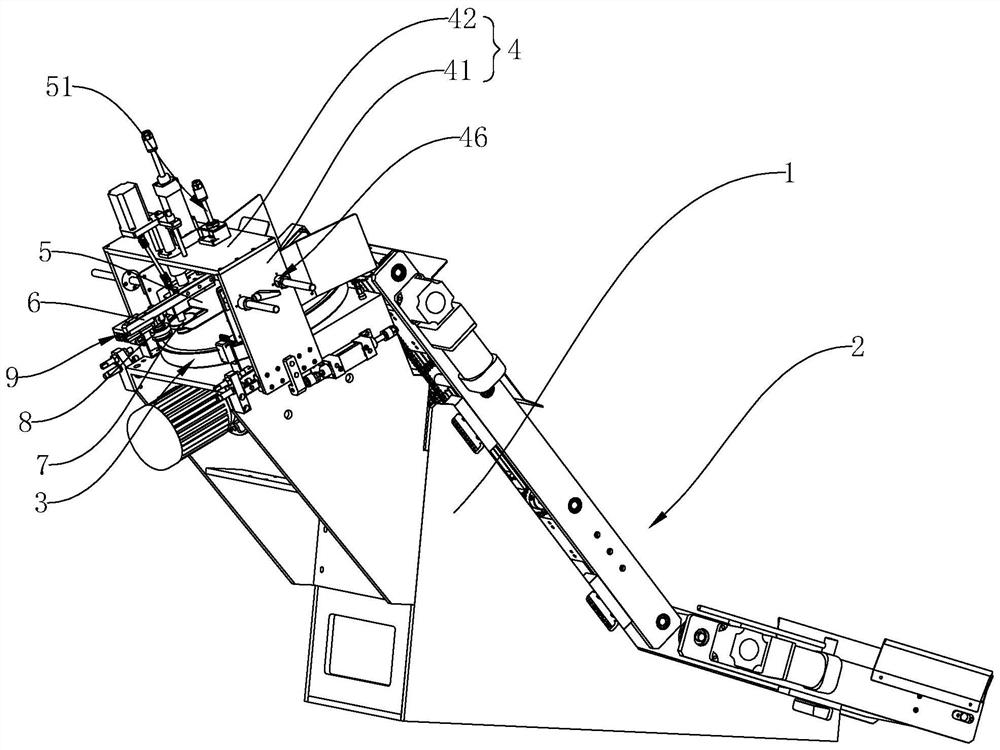
[0038] Embodiment 1: As shown in the figure, a steel ring presser foot chamfering machine includes

[0039] Rack 1;

[0040] A transmission mechanism 2, the transmission mechanism 2 is arranged on the frame 1, and is used to transmit the steel ring to be processed;

[0041] A turntable mechanism 3, the turntable mechanism 3 is arranged on the frame 1, and is used to receive the steel ring to be processed delivered by the transmission mechanism and make the steel ring to be processed rotate;

[0042] A mobile frame 4, the mobile frame 4 can move forward and backward and is arranged on the frame 1, and is located above the turntable mechanism 3;

[0043] A pressing plate 5, the pressing plate 5 is arranged on the mobile frame 4 through the lifting mechanism 51, and is used for contacting with the steel ring to be processed;

[0044] Press down bar 6, and press down bar 6 can move up and down by pressing down mechanism 61 and be arranged on moving frame 4;

[0045] A driving w...

Embodiment 2

[0049] Embodiment two: as shown in the figure, other structures are identical with embodiment one, and its difference is that transmission mechanism 2 comprises belt conveying unit 21 and chain conveying unit 22, and belt conveying unit 21 is arranged on the bottom of frame 1 back, And it is used to transport the steel rings to be processed to the entrance of the chain conveyor unit 22, the chain conveyor unit 22 is obliquely arranged on the back of the frame 1, and is used to transport the steel rings to be processed delivered by the belt conveyor unit 21 one by one to There are 3 turntable mechanisms. In this structure, the belt conveying unit 21 is an existing technology, which is used to receive the steel rings conveyed from the previous station, and then transfer them to the chain conveying unit 22, and the chain conveying unit 22 sequentially conveys the steel rings to the turntable mechanism one by one 3. The transmission process is relatively stable.

[0050] The chai...

Embodiment 3

[0051] Embodiment 3: As shown in the figure, other structures are the same as Embodiment 2. The difference is that the turntable mechanism 3 includes a mounting base 31, a first motor 32 and a rotating disk 33, and the mounting base 31 is fixed on the front of the frame 1. part, and the top of the mounting seat 31 has a fixed plate 34 inclined downwards, the rotating disk 33 is rotatably arranged on the upper end of the fixed plate 34, and the upper surface of the rotating disk 33 is provided with an accommodating chamber 35 for placing the steel ring, The first motor 32 is fixed in the mounting seat 31, and is used to drive the rotating disc 33 to rotate. The mobile frame 4 is composed of two side plates 41 and a top plate 42 fixed between the two side plates 41. The two side plates 41 are respectively The first cylinder 43 can move back and forth and is arranged on the left and right sides of the installation seat 31 , and a first guide assembly 44 is arranged between each si...


PUM


Abstract

The invention discloses a steel ring presser foot chamfering integrated machine, which comprises a frame; a transmission mechanism, which is arranged on the frame, and is used for transferring steel rings to be processed; a turntable mechanism, which is arranged on the frame The mobile frame, the mobile frame can move back and forth and is set on the frame, and is located above the turntable mechanism; the lower pressure rod, the lower pressure rod can move up and down through the lower pressure mechanism and is set on the mobile frame; the driving wheel, the driving wheel can be rotated and set At the lower end of the lower pressure rod, the lower part of the driving wheel is provided with an arc-shaped groove for pressing the steel ring, and the upper part of the driving wheel is provided with a first inclined plane; the auxiliary wheel, which can move forward and backward through the displacement mechanism, is set on the lower pressure rod The lower end of the lower end of the auxiliary wheel is close to or away from the driving wheel. The lower part of the auxiliary wheel is provided with a second slope, and a chamfering gap is formed between the first slope and the second slope; the advantages are that it can realize automatic processing, reduce labor intensity, and can Improve safety and work efficiency.

Description

technical field [0001] The invention relates to the technical field of steel ring manufacturing, in particular to a steel ring presser foot chamfering integrated machine. Background technique [0002] As the market's requirements for cooking pots are getting higher and higher, more and more merchants have introduced glass pot lids. In order to prevent the edges of the pot lids from being scratched and cracked, glass pot lids need to be made of steel rings during the manufacturing process. side. [0003] At present, in order to better fit the pot lid, the manufacturing process of the steel ring is relatively complicated. The process usually includes ringing, welding, edge pulling, curling and chamfering. The curling process is completed in a special curling device. After the edge is completed, its shape is as in the attached figure 1 As shown, at this time, the lower end of the steel ring is only bent, and workers need to take it out and put it into a special presser foot d...

Claims


Application Information

Patent Timeline
Patent Type & Authority Patents(China)
IPC IPC(8): B21D19/04B21D19/12B21D43/02B21D43/12B21D43/14B21D51/44
CPCB21D19/043B21D19/12B21D43/027B21D43/12B21D43/14B21D51/44
Inventor 王贵文
Owner NINGBO JINSHIHONG MACHINERY EQUIP CO LTD
Why Eureka
Try Eureka