
Laser cleaning method and laser cleaning system based on sheet resistance measurement

A laser cleaning and to-be-cleaned technology, applied in the field of laser cleaning, can solve the problems of complex laser cleaning process, influence of cleaning effect, complex system, etc., to achieve high measurement accuracy, reduce the risk of substrate damage, and fast response.

Active Publication Date: 2020-08-25
NORTHWEST UNIV(CN)
View PDF4 Cites 0 Cited by
  • Summary
  • Abstract
  • Description
  • Claims
  • Application Information

AI Technical Summary

Problems solved by technology

[0004] The process of laser cleaning is very complicated, and the main cleaning mechanisms are thermal expansion, vaporization, ablation and phase explosion, etc.
For different light sources, substrates, pollutants and other factors will have a greater impact on the cleaning effect
At present, the laser cleaning equipment on the market can only roughly clean the workpiece, and only rely on the operator's experience and naked eyes to judge the cleaning effect and quality, which can easily lead to substrate damage
Existing technologies use changes in signals such as spectra, acoustic waves, and reflectivity during the laser cleaning process to monitor the cleaning effect, but these methods are often costly and complex

Method used


Image

  • Laser cleaning method and laser cleaning system based on sheet resistance measurement
  • Laser cleaning method and laser cleaning system based on sheet resistance measurement
  • Laser cleaning method and laser cleaning system based on sheet resistance measurement

Examples


Embodiment Construction

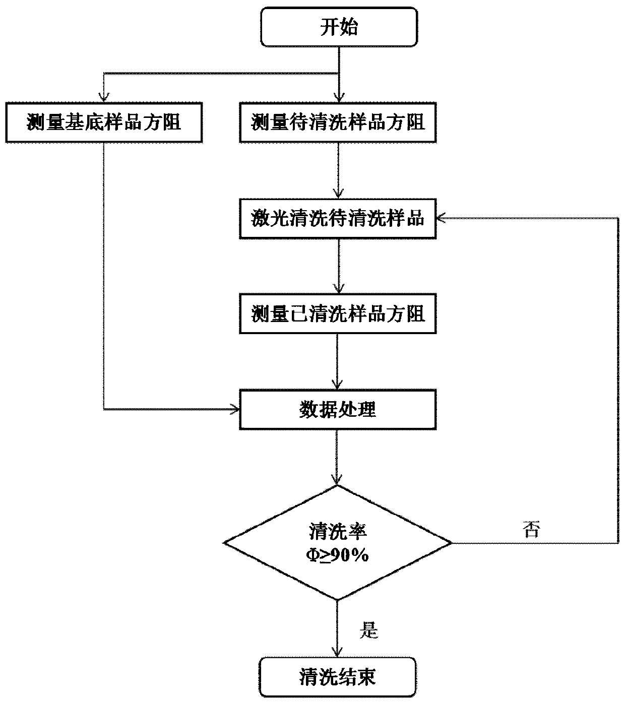
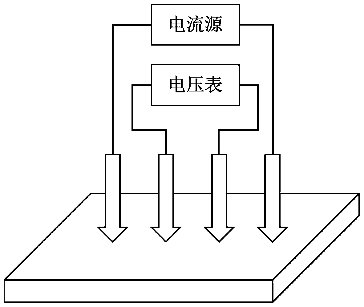
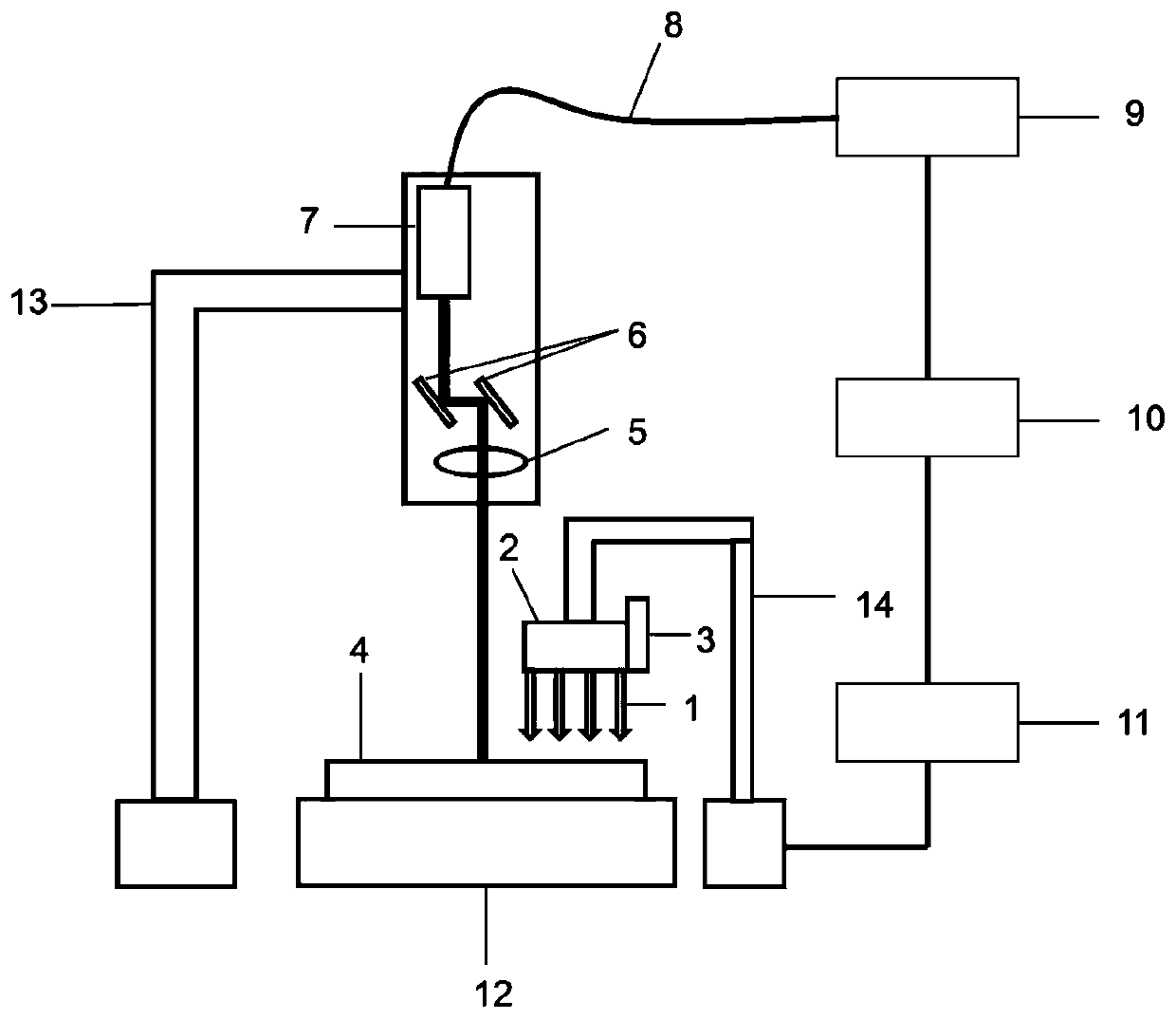
[0045] The following will refer to the attached figure 1 to attach image 3 Specific examples of the present invention are described in more detail. Although specific embodiments of the invention are shown in the drawings, it should be understood that the invention may be embodied in various forms and is not limited to the embodiments set forth herein. Rather, these embodiments are provided for more thorough understanding of the present invention and to fully convey the scope of the present invention to those skilled in the art.

[0046] It should be noted that certain terms are used in the specification and claims to refer to specific components. Those skilled in the art should understand that they may use different terms to refer to the same component. The specification and claims do not use differences in nouns as a way of distinguishing components, but use differences in functions of components as a criterion for distinguishing. "Includes" or "comprises" mentioned thro...


PUM


Abstract

The invention discloses a laser cleaning method and a laser cleaning system based on sheet resistance measurement. The method comprises the steps that a laser cleaning machine and a four-probe probe are installed to align a to-be-cleaned sample, the four-probe probe is enabled to be connected with a resistance instrument, the parameters of the laser cleaning machine is adjusted, a substrate sampleand the to-be-cleaned sample are placed on a three-dimensional platform, and the four-probe probe moves downwards to compress the surface of the sample; the sheet resistance of the substrate sample and the sheet resistance of the to-be-cleaned sample are measured respectively, the probe pressure and the surface temperature of the sample are recorded, the scanning frequency of single-time cleaningis set, and the sample is subjected to n times of laser cleaning, wherein n is a natural number; after the cleaned sample stands and is naturally cooled, under the probe pressure and the surface temperature, the resistance meter measures the sheet resistance of the sample after laser cleaning, the relative cleaning rate phi is calculated, and when the relative cleaning rate phi is larger than orequal to a preset value, it is judged that the sample is cleaned up; and when the relative cleaning rate phi is smaller than the preset value, cleaning is repeated until phi is larger than or equal tothe preset value, and cleaning is finished.

Description

technical field [0001] The invention belongs to the technical field of laser cleaning, in particular to a laser cleaning method and a laser cleaning system based on square resistance measurement. Background technique [0002] In recent years, as my country's environmental protection system has become more complete, people's awareness of environmental protection has become stronger and stronger, which has put forward higher environmental protection requirements for the industrial cleaning industry. Traditional industrial cleaning methods often have high pollution, high labor intensity, and low cleaning precision, which seriously hinder the development of modern cleaning technology. As a cleaning technology that has only emerged in recent years, laser cleaning is in sharp contrast to traditional cleaning methods such as chemical cleaning agents, ultrasonic waves, and mechanical methods because of its technical characteristics such as environmental protection, high efficiency, ...

Claims


Application Information

Patent Timeline
Patent Type & Authority Applications(China)
IPC IPC(8): B08B7/00B08B13/00G01D21/02
CPCB08B7/0042B08B13/00G01D21/02
Inventor 白杨查榕威
Owner NORTHWEST UNIV(CN)
Learn More