A spoon dyeing device

A dyeing device and spoon technology, which is applied to the device and coating of the surface coating liquid, can solve the problems of inability to uniformly control the dyeing time, time-consuming and labor-intensive problems, and achieve the effect of reducing manual operations and facilitating collection and removal

Active Publication Date: 2021-12-07
徐超
View PDF10 Cites 0 Cited by
  • Summary
  • Abstract
  • Description
  • Claims
  • Application Information

AI Technical Summary

Problems solved by technology

[0005] In order to overcome the shortcomings of current spoon dyeing which is completely done manually, which is time-consuming and laborious, and cannot evenly control the dyeing time of each group of spoons, the technical problem of the present invention is: to provide a method that reduces manual operations and can evenly control the dyeing time of each group of spoons. Time's Spoon Dyeing Apparatus

Method used


Image

  • A spoon dyeing device
  • A spoon dyeing device
  • A spoon dyeing device

Examples


Embodiment 1

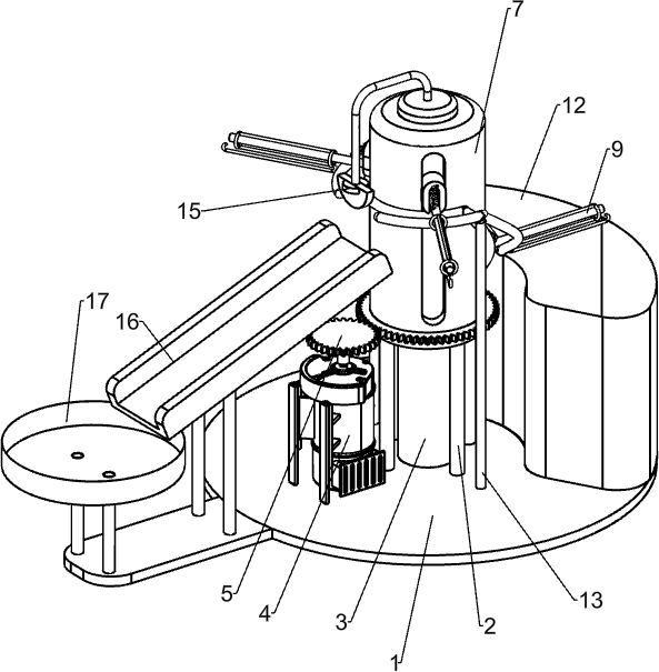
[0020] A spoon dyeing device, such as Figure 1-3 As shown, including the rack 1, the support frame 2, the cylindrical 3, the dye box 12, the power assembly, and the support assembly, the upper intermediate welding of the frame 1 is welded, and the cylindrical 3 is located in the support frame 2, the rack 1 The upper right side is placed with a dye box 12, and the upper portion of the rack 1 is provided with a power assembly that operates by the motor rotation, and the power assembly is slidably disposed.

[0021] like figure 1 with 2 As shown, the power assembly includes a reduction motor 4, a gear 5, a ring gear 6, and a rotating sleeve 7, and the upper left side of the rack 1 passes through the bolt, and the output shaft of the reduction motor 4 is connected by the rotor. The gear 5, the upper rotation of the support frame 2 is provided with a rotating sleeve 7, and the cylindrical 3 is located in the rotary sleeve 7, and the rotary sleeve 7 is connected to the ring gear 6, and ...

Embodiment 2

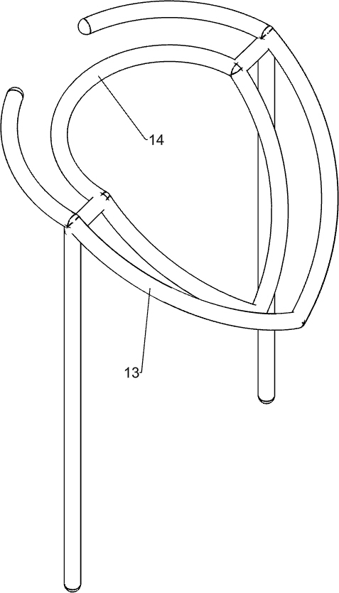
[0027] On the basis of Example 1, if figure 1 with 4 As shown, there is also included a first adjustment lever 13 and a second adjustment lever 14, and a first adjustment lever 13 is welded at the top of the frame 1, and the second adjustment lever 13 is welded in the first regulating lever 13.

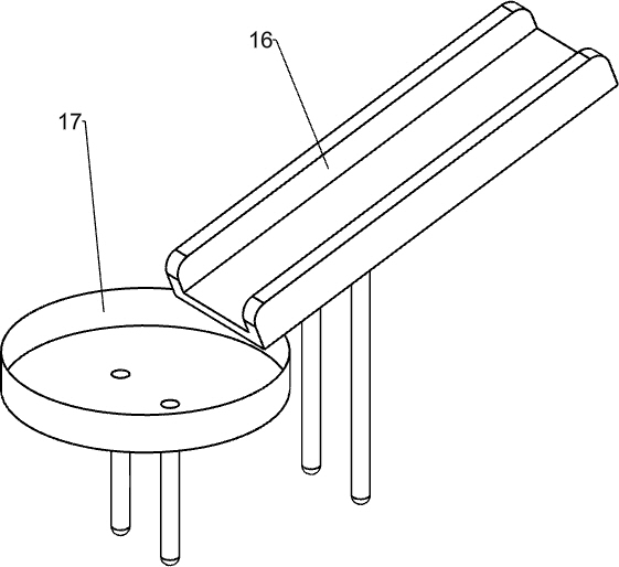
[0028] like figure 1 with 5 As shown, there is also a stopper 15, a slide 16, and a collection box 17. The left side of the top of the cylindrical 3 is welded, and the left side of the rack 1 has a slide 16, and the left side of the rack 1 is welded to the collected box 17. .

[0029] The working principle of the above embodiment: When the support assembly is moved, the slider 8 is in line with the second regulating lever 14, and as the second adjustment lever 14 is lifted down, the pendulum rod 9 drives the spoon from the dye box 12 Dye box 12, and exit from above after dyeing, preventing dye from moving out along the side wall of the dye box 12. In this process, the pendulum 9 is tightl...


PUM


Abstract

The invention relates to a dyeing device, in particular to a spoon dyeing device. The technical problem to be solved by the present invention is to provide a spoon dyeing device that reduces manual operations and can evenly control the dyeing time of each group of spoons. A spoon dyeing device, comprising: a frame; a supporting frame, installed on the frame; a cylinder, installed on the frame; a dye box, installed on the frame; a power assembly, installed on the frame; a support assembly, Sliding mounted on power pack. The present invention provides power through the power assembly, and the slider and the slider support rod cooperate to make the support assembly rotate and move up and down, and each group of spoons can be continuously put into the dye box from top to bottom, and then move up to leave the dye box , so that the dyeing time of each group of spoons can be uniformly controlled, and the dyes can be prevented from flowing out along the side wall of the dye box with the spoons, and the dyed spoons can be taken out automatically with the hooks, and stay in the collection box.

Description

Technical field [0001] The present invention relates to a dyeing apparatus, and more particularly to a spoon dyeing device. Background technique [0002] Spoon, a handleable instrument that can take something, can be said to be the most historic dining tool, and the material of the spoon mainly has plastic, wooden, stainless steel, ceramics, and spoons made with plant cach. [0003] When the spoon is made, it is shown that the color of the production material is displayed, in order to enable the spoon color, it is better to look, it is necessary to dye the spoon. The existing dyeing technology is manually hanging into the hook, then put it in the dyeing container, so that the spoon is completely soaked in a dyed liquid for a period of time, and then taken out, this dyeing method is completely carried out, time-freight, and cannot be Uniform control of the dyeing time of each set of spoons. [0004] It is therefore necessary to develop a spoon dyeing device that reduces manual ope...

Claims


Application Information

Patent Timeline
Patent Type & Authority Patents(China)
IPC IPC(8): B05C3/09B05C3/10B05C13/02
CPCB05C3/09B05C3/10B05C13/02
Inventor 刘燕娟徐超
Owner 徐超
Why Eureka
Try Eureka