
A photographic light for photography

A technology for a photographic lamp and a casing, applied in the field of photographic lamps, can solve the problems of inability to protect and not be difficult, and achieve the effect of simple structure and improved safety.

Active Publication Date: 2021-06-25
HENAN POLYTECHNIC UNIV
View PDF7 Cites 0 Cited by
  • Summary
  • Abstract
  • Description
  • Claims
  • Application Information

AI Technical Summary

Problems solved by technology

Therefore, only one of the light-shielding plates 32 needs to be adjusted, and the other light-shielding plates 32 will move together, and through the adjustment of the bevel gear, the synchronous movement of each light-shielding plate 32 can be realized, not only the swing angles are consistent, but also open together or together. closed"; the other is "does not contain the seventh bevel gear 347 and the eighth bevel gear 348, and a micro-motor 4 is installed at the position of the seventh bevel gear 347 or the eighth bevel gear 348, and the micro-motor 4 is fastened It is not difficult to see that the main purpose of the applicant in this case is to overcome the fact that the number of light baffles on a photographic lamp is four, and each adjustment needs to turn over the light baffles individually, and It needs to be adjusted four times in a row to complete the adjustment of a photographic light. It is a technical solution that can adjust the angle of the light barrier around the lens of the camera. What needs to be explained in this part is that this technical solution only considers the angle Adjustable convenience, but it completely ignores the convenience of storage and the importance of carrying after storage. Those skilled in the art should understand that since the four light baffles all use rotating shafts and bevel gears to realize four baffles When the light panels are linked, when the edges of the four light baffles are completely close together, they cannot be further folded. At this time, the space occupied by the entire photographic light is the largest. Of course, those skilled in the art can also completely outside the light baffle. Turn it over until it fits on the outer wall of the lamp body. At this time, the space occupied by the entire photography light is the smallest, but the lamp head assembly of the photography light is completely exposed, and it cannot get proper protection at all, let alone after storage. transported and carried;
[0004] The patent application document with the patent number "201920882077.4" published by the State Intellectual Property Office in 2019 and the patent name "An Anti-Glare Infrared Image Camera" provides a device that can be stored in the connection box (2) and powered by an electric The camera light baffle (8) driven by the push rod (3), it is not difficult to see that the applicant in this case uses the electric push rod (3) as an external axial driving force to push the light baffle (8) in and out, Of course, the electric push rod (3) can also be used by those skilled in the art in the technical solution of the previous paragraph to axially push one of the light baffles to achieve the technical content of the joint linkage of the other three light baffles. How to combine or superimpose technologies can not achieve the ultimate goal of fully storing the head of the photography light assembly in a relatively sealed protective cavity while folding and storing the light baffle

Method used


Image

  • A photographic light for photography
  • A photographic light for photography

Examples


Embodiment Construction

[0019] In order to make the technical means, creative features, goals and effects achieved by the present invention easy to understand, the technical solutions in the embodiments of the present invention will be clearly and completely described below in conjunction with the accompanying drawings in the embodiments of the present invention.

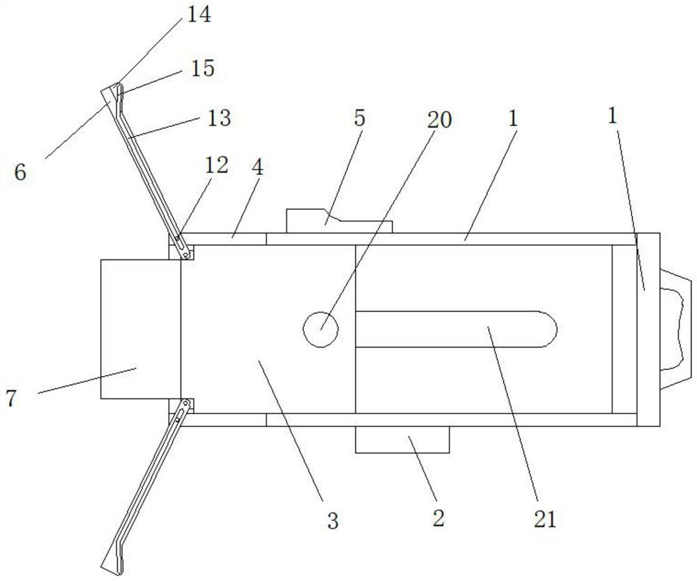
[0020] see Figure 1-2 , this specific embodiment is realized by adopting the following technical scheme, which includes a casing 1, the casing 1 is a hollow cuboid structure as a whole, and a cloud for docking with a tripod is fixedly installed on the lower bottom surface of the casing 1. Platform 2, the interior of the casing 1 is provided with a photographic light group 3 that can slide and fit with the gap, the four corners of the end of the casing 1 are respectively vertically fixed with positioning edges 4, and the outer surface of the casing 1 There is a positioning sleeve 5 that slides and fits with the gap on its outer side, and t...


PUM


Abstract

The invention discloses a photographic light for photographing and recording, which comprises a casing (1), the casing (1) is a hollow cuboid structure as a whole, and a lower bottom surface of the casing (1) is fixedly installed The cloud platform (2) used for docking with a tripod, the inside of the casing (1) is provided with a photographic light group (3) that can slide and fit with the gap, and the four corners of the end of the casing (1) are respectively A positioning edge (4) is vertically fixed, and a positioning sleeve (5) is provided on the outer surface of the casing (1) to slide and fit with the outer surface thereof. The invention has a simple structure, and can effectively adjust the opening and closing angle of the light baffle according to needs during use. At the same time, no matter how the light baffle is adjusted, the head of the photographic light group is always at the most ideal position, and the four baffles After the light board is fully folded and stored, the entire photographic light group is in a relatively sealed casing, which greatly improves the safety during transportation.

Description

technical field [0001] The present invention relates to the field of equipment related to photography, in particular to a photography light for photography and photography. Background technique [0002] In the face of most cases of insufficient light, it is usually necessary to use the help of a photography light. The photography light can obviously increase the exposure of the under-light part of the subject, so as to achieve the effect of supplementary light. Because the photography light is only to improve the under-light part of the subject That is to say, only a certain part needs to be irradiated by the photographic light. For this reason, a circle of light baffles will be set around the lampshade of the common photographic lights at present. Most of the light baffles are black, and the main purpose is to reduce light. Shade is used to reduce the amount of light, so some workers in the circle also call it "light-absorbing board" and "light-reducing board". In addition,...

Claims


Application Information

Patent Timeline
Patent Type & Authority Patents(China)
IPC IPC(8): G03B15/03G03B15/06
CPCG03B15/03G03B15/06
Inventor 梁婷婷刘照国
Owner HENAN POLYTECHNIC UNIV
Learn More