
Calculation method for energy flow decoupling analysis of distributed cogeneration integrated energy system

A technology of integrated energy system and cogeneration of cooling, heating and power, which is applied in the direction of calculation, AC network with different sources of the same frequency, resources, etc., can solve problems such as slow solution speed, poor convergence, complex algorithm, etc., and achieve fast solution speed , the algorithm is simple and easy to understand, and the effect of solving simplification

Active Publication Date: 2022-06-17
海宁云多科技有限公司
View PDF5 Cites 0 Cited by
  • Summary
  • Abstract
  • Description
  • Claims
  • Application Information

AI Technical Summary

Problems solved by technology

The problems of the existing solution methods mainly include: (1) whether it is a joint solution or an iterative solution, the algorithm is very complicated, the convergence is poor, and the solution speed is slow; (2) when the grid load is large and the lines between nodes are short, the Newton- Raphson’s method may not be able to solve it; (3) Traditional large-scale thermal systems usually adopt the mode of “heating to determine power”, and the solution method of its mathematical model is not suitable for integrated energy systems, because the distributed power generation of combined cooling, heating and power and Conventional thermal power units are quite different, especially fuel cells; (4) The coupling relationship between the distributed power supply and independent electric cooling / heating equipment (such as: air conditioners, water heaters) and distributed cooling are not considered. / thermal application scenarios

Method used


Image

  • Calculation method for energy flow decoupling analysis of distributed cogeneration integrated energy system
  • Calculation method for energy flow decoupling analysis of distributed cogeneration integrated energy system

Examples


Embodiment Construction

[0031] The present invention will be further described below in conjunction with the accompanying drawings.

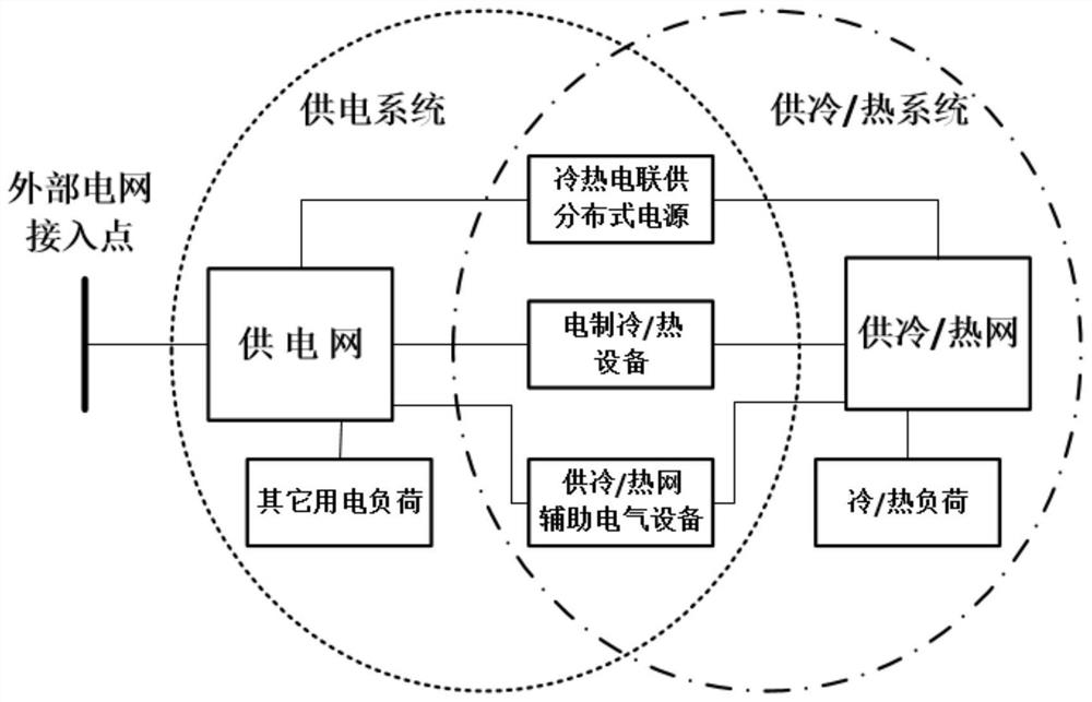
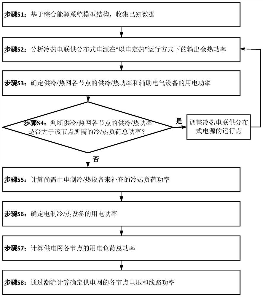
[0032] refer to figure 1 and figure 2 , an energy flow decoupling analysis and calculation method for a distributed combined cooling, heating and power integrated energy system, comprising the following steps:

[0033] Step S1, based on the comprehensive energy system model structure, collect known data, including system parameters and some operating variables;

[0034] Step S2, analyzing the output waste heat power of the combined cooling, heating and power distributed power supply under the operation mode of "fixing heat by electricity";

[0035] The output waste heat power of the combined cooling, heating and power distributed power generation in the operation mode of "fixing heat by electricity" can be obtained by the detailed system modeling analysis of the distributed power generation, or it can be solved by the following simplified formula: :

[0036] Φ DG...


PUM


Abstract

A method for decoupling analysis and calculation of energy flow in a distributed combined cooling, heating and power integrated energy system, including cooling / heating / grid and auxiliary electrical equipment, distributed power sources for combined cooling, heating and power, and independent electric cooling / heating equipment. Know the voltage amplitude and phase angle of the connection point between the integrated energy network and the external power grid, the power load power of each node of the power supply network except for the electric cooling / heating equipment and the auxiliary electrical equipment of the cooling / heating network, and the power generation of each distributed power supply Power, the supply / return temperature of the node where the distributed power supply in the cooling / heating network is located, the total power of the cooling / heating load required by each node of the cooling / heating network, and the cooling / heating / grid network Characteristic parameters, solve the voltage and line power of each node of the power supply network in the integrated energy system, the cooling / heating power of each node of the cooling / heating network and the power consumption of auxiliary electrical equipment. The energy flow analysis and calculation method of the present invention is more in line with the requirements of actual application scenarios, and the algorithm is simple and easy to understand, and the solution speed is fast.

Description

technical field [0001] The invention relates to the field of integrated energy system of combined cooling, heating and power, in particular to a method for decoupling analysis and calculation of energy flow of a distributed combined cooling, heating and power integrated energy system. Background technique [0002] Cogeneration gas turbines, fuel cells and other distributed power sources, combined with heat pump air conditioners, absorption refrigeration equipment, heat exchangers and other waste heat utilization refrigeration / heating devices, the active microgrid including wind-light-storage is gradually moving towards distributed cooling and heating power Joint supply integrated energy system development direction. The integrated energy system can not only provide electricity, but also meet the local cooling / heating load demand. The cascade utilization of energy realizes the efficient conversion and utilization of primary energy, improves the reliability of the energy syste...

Claims


Application Information

Patent Timeline
Patent Type & Authority Patents(China)
IPC IPC(8): H02J3/06H02J3/28G06Q10/06G06Q50/06
CPCH02J3/06H02J3/28G06Q10/06312G06Q50/06H02J2203/10H02J2300/00Y02P90/82
Inventor 戚军童辉周丹
Owner 海宁云多科技有限公司
Learn More