
Electric actuating mechanism and valve connection state detection device and method

A technology for electric actuators and connection states, applied in measuring devices, force/torque/power measuring instruments, instruments, etc., can solve the problems of lye pump damage, large vibration, and failure to open, etc., and achieve high torque detection accuracy, High cost and good stability

Pending Publication Date: 2020-08-18
刘建松 +1
View PDF0 Cites 1 Cited by
  • Summary
  • Abstract
  • Description
  • Claims
  • Application Information

AI Technical Summary

Problems solved by technology

[0002] With the development of industrial intelligence, there are more and more automatic interlocking and sequential control functions of equipment in the industrial production process. When starting pumps, fans and other equipment in chains, it is necessary to open the entrance and exit electric doors in advance. When desulfurizing the slurry pump, it is necessary to close the slurry discharge door in advance and open the electric door of the slurry pump inlet. In the actual production process, it was found that the actuator of the slurry pump inlet electric door had been opened in place. After the slurry pump was connected, the vibration was large and the alkali pump was damaged. , the accident analysis found that the imported electric door actuator of the slurry pump was working normally, but the deceleration mechanism between the electric actuator and the valve was disengaged. Although the electric actuator was working normally, the valve was not opened, causing damage to important equipment. There are many such problems in the production process, and there are the same hidden dangers

Method used


Image

  • Electric actuating mechanism and valve connection state detection device and method
  • Electric actuating mechanism and valve connection state detection device and method
  • Electric actuating mechanism and valve connection state detection device and method

Examples


Embodiment Construction

[0021] In order to make the purpose, technical solution and advantages of the present application clearer, the embodiments of the present application will be further described in detail below in combination with specific embodiments and with reference to the accompanying drawings.

[0022] It should be noted that all expressions using "first" and "second" in the embodiments of this application are to distinguish between two entities with the same name but different parameters or parameters that are not the same, see "first" and "second" It is only for the convenience of expression, and should not be construed as a limitation on the embodiments of the present application, which will not be described one by one in the subsequent embodiments.

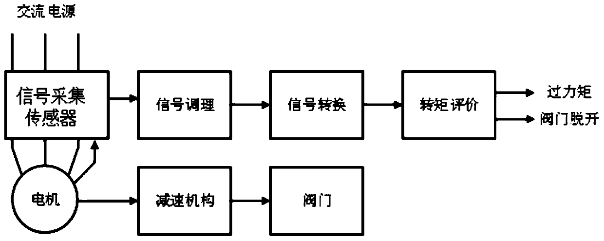
[0023] In order to solve the technical problems mentioned in the background technology, this application designs a device and method for detecting the connection state between the electric actuator and the valve, specifically by detecting t...


PUM


Abstract

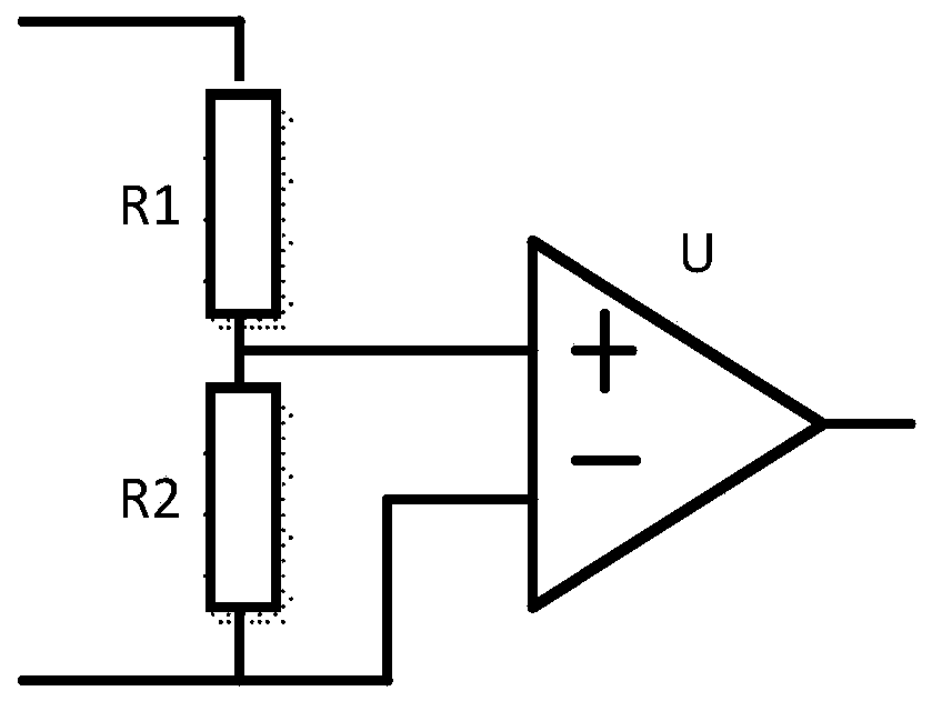
The invention provides an electric actuating mechanism and valve connection state detection device and method, and the device comprises a plurality of signal collection sensors, a signal conditioningcircuit, a signal conversion circuit, and a control module. And each signal collection sensor is respectively connected with the signal conditioning circuit, the signal conversion circuit and the control module in sequence. The method comprises the following steps: acquiring a plurality of electric signals in the electric actuating mechanism; inputting the various electric signals into a neural network model obtained through pre-training to obtain an instantaneous torque output value; and comparing the instantaneous torque output value with a preset torque range, and judging the connection state of the electric actuating mechanism and the corresponding valve. The instantaneous torque on the output shaft of the electric actuating mechanism is obtained through the current signal, the voltagesignal, the rotating speed signal and the neural network model, and based on accurate detection of the instantaneous torque, accurate judgment of the connection state of the electric actuating mechanism and the valve is achieved.

Description

technical field [0001] The application relates to the field of signal processing and automatic control, and specifically relates to a device and method for detecting the connection state of an electric actuator and a valve, which are used to accurately detect the connection state of an electric actuator and a valve. Background technique [0002] With the development of industrial intelligence, there are more and more automatic interlocking and sequential control functions of equipment in the industrial production process. When starting pumps, fans and other equipment in chains, it is necessary to open the entrance and exit electric doors in advance. When desulfurizing the slurry pump, it is necessary to close the slurry discharge door in advance and open the electric door of the slurry pump inlet. In the actual production process, it was found that the actuator of the slurry pump inlet electric door had been opened in place. After the slurry pump was connected, the vibration ...

Claims


Application Information

Patent Timeline
IPC IPC(8): G01L5/00G01D21/02
CPCG01D21/02G01L5/0061G01L5/0071
Inventor 刘建松张庆军刘怡琳甘良清
Owner 刘建松
Learn More