A tunnel furnace drying system

A technology of drying system and tunnel furnace, which is applied in the direction of drying, drying machine, progressive drying machine, etc., which can solve the problems of labor and material cost, large amount of ammonia gas generation, and poor human health, so as to save manpower and material costs, improve uniformity, and reduce pollution effects

Active Publication Date: 2021-07-02
包头市海罗水泥制品机械有限公司
View PDF5 Cites 0 Cited by
  • Summary
  • Abstract
  • Description
  • Claims
  • Application Information

AI Technical Summary

Problems solved by technology

Therefore, there are following defects: (1) the natural drying process can produce a large amount of ammonia gas, pollute the environment, (2) people can inhale ammonia gas in the carrying process, which is bad for people's health
In addition, the existing tunnel-type drying system mostly uses a mesh conveyor belt to transport and dry materials, which requires manual placement of the materials on the conveyor belt one by one, and the dried materials need to be taken out again at the discharge end. It takes a lot of manpower and material costs to put it in the corresponding material box and re-transport it, and the workers are in this environment for a long time, and it is easy to cause harm to the body
(3) In the process of frequent transshipment, some debris will inevitably be produced. After drying, special cleaning must be carried out to improve the cleanliness of the product, which is time-consuming and laborious

Method used


Image

  • A tunnel furnace drying system
  • A tunnel furnace drying system
  • A tunnel furnace drying system

Examples


Embodiment Construction

[0028] In order to make the technical means, creative features, goals and effects achieved by the present invention easy to understand, the present invention will be further described below in conjunction with specific embodiments.

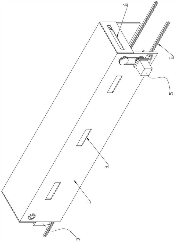
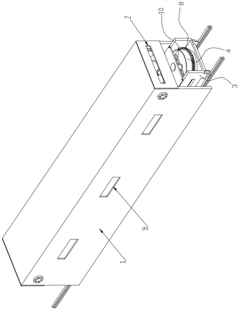
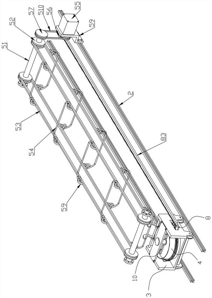
[0029] like Figure 1 to Figure 9 As shown, a tunnel furnace drying system includes a furnace body 1, a track 2, a charging car 3, a loading tray 4, and a drive mechanism 5. The furnace body 1 and the track 2 are all installed on the ground, and the track 2 Wrapped in the furnace body 1, the two ends of the furnace body 1 are respectively provided with an air inlet 6 and an air outlet 7, and the position of the air inlet 6 is located at the outlet end of the furnace body 1, and the air outlet 7 is also connected to the ammonia removal tower to To realize the treatment of waste gas, the charging car 3 is located on the track 2 and can travel along the track 2 under the action of the driving mechanism 5, and the loading tray 4 can rotate by means of...


PUM


Abstract

The invention discloses a tunnel furnace drying system, which relates to the field of tunnel furnace equipment, including a furnace body, a track, a charging car, a loading tray and a driving mechanism. The invention optimizes the structural design of the existing tunnel furnace, adopts The operation mode of body + track + car body, that is, the material is always located on the loading tray of the car body (that is, the transfer equipment). After drying, it is transferred to the next station for subsequent processing. Compared with the traditional mesh conveyor belt The unique conveying method saves the process of repeated loading and unloading, saves manpower and material costs, and has fast drying speed, convenient operation and simple structure.

Description

technical field [0001] The invention belongs to the field of tunnel furnace equipment, and in particular relates to a tunnel furnace drying system. Background technique [0002] At present, most of the drying equipment for the anode protection ring of the unburned brick machine in the aluminum factory adopts the natural drying method on the market. If the natural drying method is adopted, the drying system is generally not equipped with ammonia removal equipment. Therefore, there can be following defects: (1) natural dry process can produce a large amount of ammonia gas, pollutes environment, (2) people can inhale ammonia gas in the carrying process, which is bad for people's health. In addition, the existing tunnel-type drying system mostly uses a mesh conveyor belt to transport and dry materials, which requires manual placement of the materials on the conveyor belt one by one, and the dried materials need to be taken out again at the discharge end. It takes a lot of manpo...

Claims


Application Information

Patent Timeline
Patent Type & Authority Patents(China)
IPC IPC(8): F26B15/14F26B25/18F26B25/00F26B25/02F26B25/04F26B21/00
CPCF26B15/14F26B21/00F26B25/001F26B25/02F26B25/04F26B25/18
Inventor 杜杰
Owner 包头市海罗水泥制品机械有限公司
Why Eureka
Try Eureka