
Blank and bottle taking and conveying device of bottle blowing machine

A blow molding machine and installation hole technology, applied in the direction of conveyors, conveyor objects, transportation and packaging, etc., can solve the problems of turntable offset, high fastening requirements, noise, vibration increase, etc., to achieve convenient installation and positioning Effect

Pending Publication Date: 2020-08-18
HEFEI ZHONGCHEN LIGHT IND MACHINERY
View PDF1 Cites 1 Cited by
  • Summary
  • Abstract
  • Description
  • Claims
  • Application Information

AI Technical Summary

Problems solved by technology

There are the following problems in the installation and debugging process: when the position of the manipulator needs to be adjusted, the screw on the expansion sleeve needs to be loosened, the turntable is turned to reposition, and the screw is tightened after the positioning is completed. The solid requirements are high, and the fastening is time-consuming. When the screws are tightened, the turntable is also prone to offset (not parallel to the cam), so that the axes of the front and rear bearings of the manipulator are not parallel to the guide rail surface of the cam, and the bearings are easily damaged. Noise, Vibration increases; usually after adjusting the position of the manipulator, the previously determined position will change during the process of tightening the expansion sleeve, and the expansion sleeve needs to be loosened again, which is cumbersome to adjust

Method used


Image

  • Blank and bottle taking and conveying device of bottle blowing machine
  • Blank and bottle taking and conveying device of bottle blowing machine
  • Blank and bottle taking and conveying device of bottle blowing machine

Examples


Embodiment Construction

[0024] The following will clearly and completely describe the technical solutions in the embodiments of the present invention with reference to the accompanying drawings in the embodiments of the present invention. Obviously, the described embodiments are only some, not all, embodiments of the present invention. Based on the embodiments of the present invention, all other embodiments obtained by persons of ordinary skill in the art without creative efforts fall within the protection scope of the present invention.

[0025] In describing the present invention, it is to be understood that the terms "opening", "upper", "lower", "thickness", "top", "middle", "length", "inner", "surrounding" etc. Indicating orientation or positional relationship is only for the convenience of describing the present invention and simplifying the description, and does not indicate or imply that the components or elements referred to must have a specific orientation, be constructed and operated in a sp...


PUM


Abstract

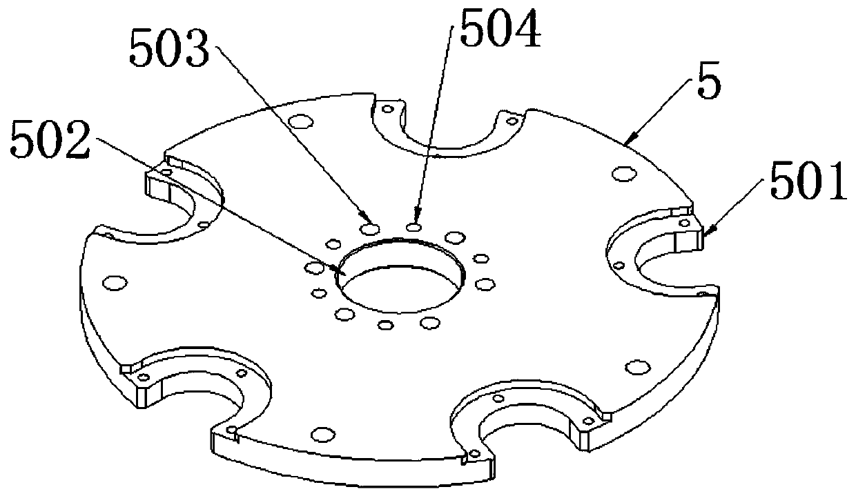
The invention discloses a blank and bottle taking and conveying device of a bottle blowing machine, and relates to the technical field of bottle blowing machine equipment. The blank and bottle takingand conveying device of the bottle blowing machine comprises a cam plate, the cam plate is fixed to a supporting column, one end of a shaft body installed inside the supporting column extends out of agroove hole, the extending end of the shaft body is arranged with a tray in a sleeve mode, a rotary plate is placed on the tray, an adjusting plate is installed on the rotary plate, the threaded endof a fixing screw sequentially penetrating through a long kidney-shaped hole in the adjusting plate and a screw installation hole in the rotary plate is fixedly installed in a screw hole in the tray,the extending end of the shaft body penetrates through a through hole of the rotary plate and extends into a stepped hole of the adjusting plate, an expansion sleeve is fixedly installed at the extending end and is tightly installed in the stepped hole, a plane is arranged on the circumferential side face of the adjusting plate, two protrusions are symmetrically arranged on the plane, and meanwhile adjusting screws making contact with positioning rods are installed in protruding adjusting screw installing holes. According to the blank and bottle taking and conveying device of the bottle blowing machine, a fine adjustment mechanism is arranged between the rotary plate and a cam, so that the manipulator rotary plate can be conveniently installed and positioned for the first time and can be conveniently repositioned and adjusted after being maintained.

Description

technical field [0001] The invention belongs to the technical field of bottle blowing machine equipment, and in particular relates to a device for fetching and feeding blanks and bottles of a bottle blowing machine. Background technique [0002] In our life, we use a lot of plastic bottles, not only when we drink beverages, but also in other industries and fields. Plastic bottles or plastic containers, plastic containers Not only is it light in weight and easy to carry, it is widely respected by the masses, but these plastic containers are all blown by blow molding machines when they are made. [0003] In the prior art, the utility model patent of Chinese Patent No. CN204725826U discloses a blow molding machine manipulator support mechanism, including a cam and a drive shaft movably arranged in the cam, a support disc is connected to the drive shaft, and a manipulator is arranged on the support disc. , the connection structure between the transmission shaft and the support ...

Claims


Application Information

Patent Timeline
IPC IPC(8): B65G47/90
CPCB65G47/904B65G2201/0244
Inventor 何胜项兴龙黄卫罗兵香
Owner HEFEI ZHONGCHEN LIGHT IND MACHINERY
Learn More