Flatcar chassis overturning device

A technology of turning over device and chassis, applied in auxiliary devices, auxiliary welding equipment, welding/cutting auxiliary equipment, etc., can solve the problems of increasing difficulty in adjustment and repair, distortion of chassis composition, hidden safety hazards, etc., and achieve convenient installation and positioning operation. , Guarantee the welding quality and avoid the effect of welding deformation

Active Publication Date: 2018-12-07
CRRC TAIYUAN CO LTD
View PDF6 Cites 1 Cited by
  • Summary
  • Abstract
  • Description
  • Claims
  • Application Information

AI Technical Summary

Problems solved by technology

[0002] Laaers 5.854 flat car chassis is composed of no middle beam welding structure, which is easily affected by welding deformation, and the dimensional accuracy requirements are high, and the dimensional tolerance is within ±5mm, and the car body is divided into straight end and oblique straight end. There is a height difference between the two ends of the head, and the existing flip tires with the same height of the shaft cannot meet the flip welding requirements.
If the more common roller-type flip welding is used at present, it can only be flipped simply by controlling the two end points, and the other positions are in an unconstrained free state. During the welding process, welding deformation is likely to occur, causing distortion of the chassis composition, and deflection prefabrication cannot be performed. Increased the difficulty of post-adjustment
If the crane is used to lift and flip the welding, it will not only pose a safety hazard, but also cannot control the welding deformation

Method used


Image

  • Flatcar chassis overturning device
  • Flatcar chassis overturning device
  • Flatcar chassis overturning device

Examples


Embodiment

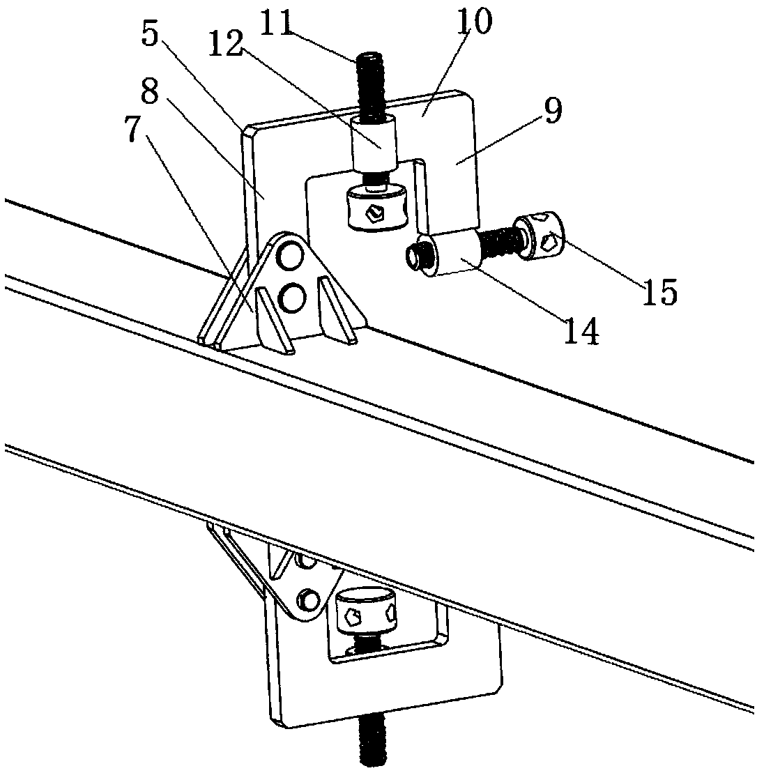
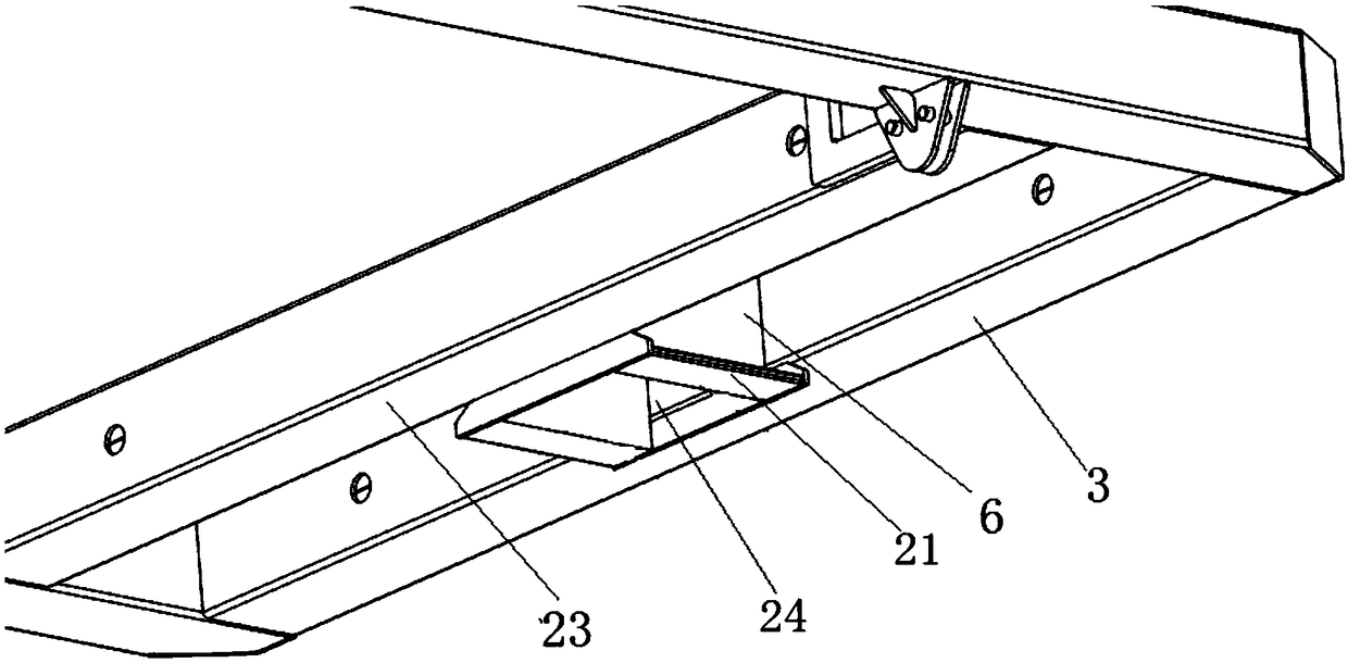
[0054] figure 1 It shows a schematic structural view of the underframe turning device of a flat car in one embodiment of the present invention, figure 2 shows a schematic structural view of the support positioning mechanism in one embodiment of the present invention, image 3 A schematic structural view of the flipped tire connector in one embodiment of the present invention is shown, Figure 4 A schematic structural view of the flip tire fixing frame in one embodiment of the present invention is shown, Figure 5 A schematic diagram of the installation of the flipped tire fixing frame and the flipped tire connecting frame in one embodiment of the present invention is shown, Figure 6 A schematic diagram of the installation of the partial frame of the underframe of the flat car and the support positioning mechanism in one embodiment of the present invention is shown.

[0055] Such as Figures 1 to 6 Shown, a kind of flat car underframe turnover device of the present invent...


PUM


Abstract

The invention provides a flatcar chassis overturning device. The flatcar chassis overturning device comprises an overturning frame, multiple support positioning mechanisms, and overturning mold connecting frames, wherein the overturning frame is a rectangular frame, and comprises a pair of side beams oppositely arranged and a pair of end beams perpendicular between the pair of side beams; the multiple support positioning mechanisms are symmetrically arranged on the side beams in the length directions of the pair of side beams; the support positioning mechanisms comprise support frames connected with the side beams, and support modules and clamping modules arranged on the support frames; the support modules and the clamping modules are used for supporting, clamping and positioning long edges on two sides of a flatcar chassis; the overturning mold connecting frames are arranged on the end beams; the multiple support positioning mechanisms are arranged in the length directions of the sidebeams of the overturning frame; and the support modules and the clamping modules of the support positioning mechanisms are arranged on the pair of side beams through the support frames for constraining the degree of freedom of the flatcar chassis frame from two directions to realize support and clamping of the flatcar chassis, so that the flatcar chassis is located in a constraint state in the welding process, the welding deformation is prevented, and the welding quality is guaranteed.

Description

technical field [0001] The invention belongs to the field of welding devices for underframe structures without center beams, and more specifically relates to an overturning device for underframes of flat cars. Background technique [0002] Laaers 5.854 flat car chassis is composed of no middle beam welding structure, which is easily affected by welding deformation, and the dimensional accuracy requirements are high, and the dimensional tolerance is within ±5mm, and the car body is divided into straight end and oblique straight end. There is a difference in height between the two ends of the headstock, and the existing flip tires with the same height of the rotating shaft cannot meet its flip welding requirements. If the more common roller-type flip welding is used at present, it can only be flipped simply by controlling the two end points, and the other positions are in an unconstrained free state. During the welding process, welding deformation is likely to occur, causing d...

Claims


Application Information

Patent Timeline
Patent Type & Authority Applications(China)
IPC IPC(8): B23K37/047
CPCB23K37/047
Inventor 郭世江原王明梁建平张利东梁巍岭王有斌成宝赟刘玉宏徐文杰
Owner CRRC TAIYUAN CO LTD
Why Eureka
Try Eureka