Catkin removing device for environmental protection
A cleaning device and technology for environmental protection, applied in road cleaning, cleaning methods, construction, etc., can solve the problems of low cleaning efficiency, small cleaning range, and inability to clean catkins, so as to reduce cleaning costs, low labor costs, and avoid The effect of bruising pedestrians
- Summary
- Abstract
- Description
- Claims
- Application Information
AI Technical Summary
Problems solved by technology
Method used
Image
Examples
Embodiment 1
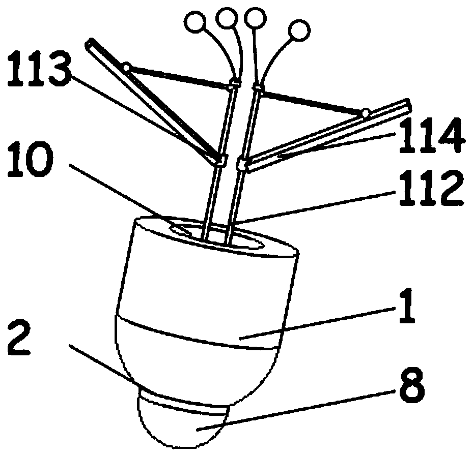
[0025] see Figure 1-2 , the present invention provides a technical solution: a catkin removal device for environmental protection, comprising a casing 1, a rubber block 8 is installed on the bottom of the casing 1, a rotating groove 10 is provided on the top of the casing 1, and the top of the inner wall of the rotating groove 10 rotates Connected with a rotating plate 111, the top of the rotating plate 111 is symmetrically equipped with a vertical rod 112, the outer side of the vertical rod 112 is covered with a sliding sleeve 113, the outer side of the sliding sleeve 113 is connected with a wing plate 114, and the top end of the vertical rod 112 passes through the limiter. The positioning bar 115 is rotatably connected with the wing plate 114 , and the top of the vertical bar 112 is fixedly connected with a baffle plate 116 .
[0026] When in use, the rubber block 8 is hit downward, and the rubber block 8 is squeezed and deformed to bounce the shell 1 into the air. When the...
Embodiment 2
[0028] see Figure 1-3 , the present invention provides a technical solution: on the basis of Embodiment 1, an elastic groove 2 is provided at the bottom of the housing 1, a motor 3 is fixedly connected to the top of the inner wall of the elastic groove 2, and a threaded rod 4 is connected to the output end of the motor 3 for transmission. , the outer side of the threaded rod 4 is provided with a lifting block 5, one side of the lifting block 5 is fixedly connected with a transmission rod 6, and the transmission rod 6 is slidingly connected with the inner wall of the elastic groove 2, and the bottom of the transmission rod 6 is fixedly connected with a connecting rod 7. Rubber blocks8.
[0029] When in use, the motor 6 starts to drive the threaded rod 4 to rotate, the lifting block 5 descends along the threaded rod 4, and presses the rubber block 8 downward, so that the rubber block 8 generates a downward force and hits the ground so that the device rises to a high altitude to...
Embodiment 3
[0031] see Figure 1-3 , the present invention provides a technical solution: on the basis of Embodiment 2, a piezoelectric material plate 901 is installed on the inner wall of the elastic groove 2, and the piezoelectric material plate 901 is slidingly connected with the inner wall of the elastic groove 2, and the piezoelectric material plate 901 Both ends of the top are electrically connected to the motor 3 through wires 902 , a magnet block 903 is slidably connected to the top of the transmission rod 6 , and a metal ring 904 is fixedly connected to the top of the piezoelectric material plate 901 , and the metal ring 904 is connected to the magnet block 903 .
[0032]When in use, when the shell 1 collides with the ground, the shell 1 squeezes the piezoelectric material plate 901 inwardly, and the piezoelectric material plate 901 contacts and squeezes the transmission rod 6 to generate current, and the motor 3 and the piezoelectric material plate 901 are formed by wires. After...
PUM
 Abstract
Description
Claims
Application Information
 - R&D
- Intellectual Property
- Life Sciences
- Materials
- Tech Scout
- Unparalleled Data Quality
- Higher Quality Content
- 60% Fewer Hallucinations
Browse by: Latest US Patents, China's latest patents, Technical Efficacy Thesaurus, Application Domain, Technology Topic, Popular Technical Reports.
© 2025 PatSnap. All rights reserved.Legal|Privacy policy|Modern Slavery Act Transparency Statement|Sitemap|About US| Contact US: help@patsnap.com


