
Optical storage method and system for introducing fluorescence signal into anisotropic structure

An anisotropic and fluorescent signal technology, applied in the field of optical storage, can solve the problem that the storage capacity needs to be further improved, and achieve the effect of convenient regulation, reliability, and large capacity.

Active Publication Date: 2020-08-14
HUAZHONG UNIV OF SCI & TECH
View PDF7 Cites 1 Cited by
  • Summary
  • Abstract
  • Description
  • Claims
  • Application Information

AI Technical Summary

Problems solved by technology

Five-dimensional optical storage has greatly increased the storage capacity, but compared with the explosive growth of data volume, the storage capacity still needs to be further improved

Method used


Image

  • Optical storage method and system for introducing fluorescence signal into anisotropic structure
  • Optical storage method and system for introducing fluorescence signal into anisotropic structure

Examples


Embodiment Construction

[0030] In order to make the object, technical solution and advantages of the present invention clearer, the present invention will be further described in detail below in conjunction with the accompanying drawings and embodiments. It should be understood that the specific embodiments described here are only used to explain the present invention, not to limit the present invention. In addition, the technical features involved in the various embodiments of the present invention described below can be combined with each other as long as they do not constitute a conflict with each other.

[0031] In the present invention, the terms "first", "second" and the like (if any) in the present invention and drawings are used to distinguish similar objects, and are not necessarily used to describe a specific order or sequence.

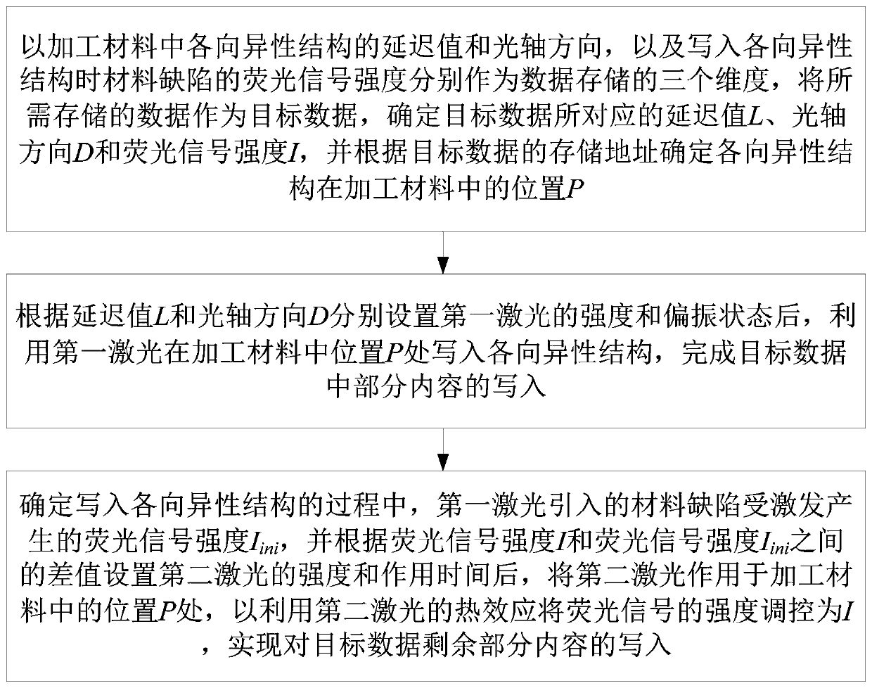
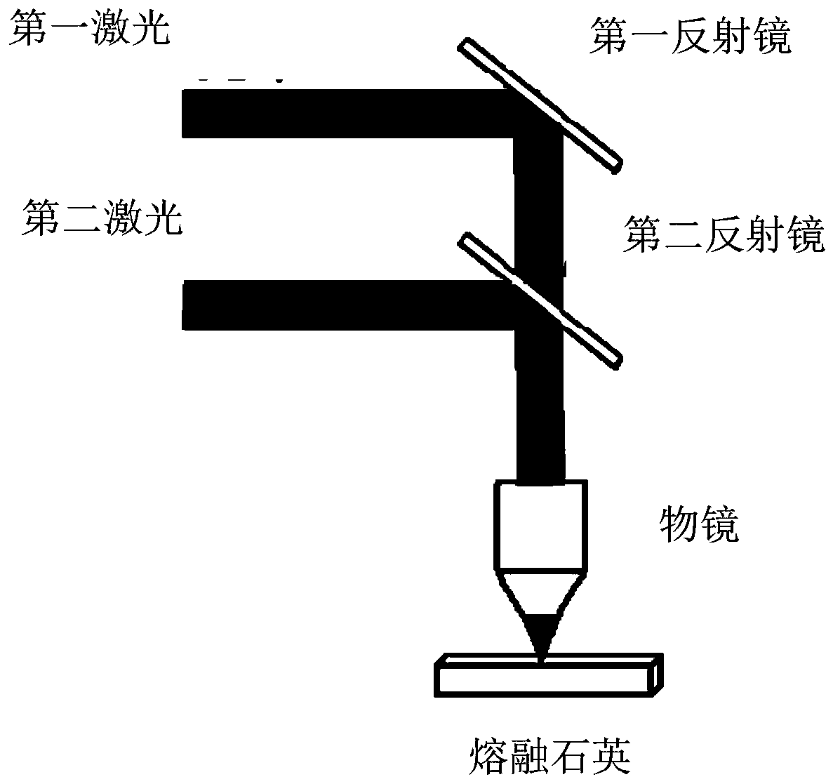
[0032] In order to further improve the capacity of optical storage, in one embodiment of the present invention, an optical storage method of introducing fluorescen...


PUM


Abstract

The invention discloses an optical storage method and system for introducing a fluorescence signal into an anisotropic structure and belongs to the field of optical storage. The method comprises the following steps: taking data to be stored as target data, determining a delay value L, an optical axis direction D and fluorescence signal intensity I corresponding to the target data, and determininga position P of an anisotropic structure in a processing material according to a storage address of the target data; respectively setting the intensity and polarization state of the first laser according to the delay value L and the optical axis direction D, and writing an anisotropic structure at the position P in the processing material by utilizing the first laser; determining the writing process of the anisotropic structure; exciting material defects introduced by the first laser to generate fluorescence signal intensity Iini; after the intensity and action time of the second laser are setaccording to the difference value between the fluorescence signal intensity I and the fluorescence signal intensity Iini, enabling the second laser to act on the position P in the machined material,so that the intensity of the fluorescence signal is regulated and controlled to be I by utilizing the heat effect of the second laser. The optical storage capacity can be improved.

Description

technical field [0001] The invention belongs to the field of optical storage, and more specifically relates to an optical storage method and system for introducing fluorescent signals into an anisotropic structure. Background technique [0002] In recent years, with the rapid development of information technologies such as the Internet and the Internet of Things, the amount of data generated by humans in production and life has also exploded. For enterprises, data centers and other institutions, how to effectively save these massive data is an important challenge. The current mainstream storage technologies often have certain disadvantages when faced with new demands. For example, hard disks such as common HDD (Hard Disk Drive, hard disk drive), SSD (Solid State Drive, solid state drive) need to consume a lot of power during use, and the service life of these devices is not long, and need to be replaced every 3 to 5 years. Data is transcribed and not suitable for long-term...

Claims


Application Information

Patent Timeline
IPC IPC(8): G11B7/126G11B7/1362
CPCG11B7/126G11B7/1362
Inventor 张静宇高骥超刘思垣
Owner HUAZHONG UNIV OF SCI & TECH
Learn More