
Redundant robot inverse kinematics solving method and device and redundant robot

A technology of inverse kinematics and robotics, applied in the field of redundant robots, can solve problems such as uncontrollable results, robot joint angles that easily exceed the working range, and robot shaking, etc., to achieve intuitive understanding

Active Publication Date: 2020-08-14
UBTECH ROBOTICS CORP LTD
View PDF6 Cites 15 Cited by
  • Summary
  • Abstract
  • Description
  • Claims
  • Application Information

AI Technical Summary

Problems solved by technology

However, the disadvantage of this calculation method is that the calculation amount is large, the setting of the gain matrix needs to consider the system computing power, and the result of the iteration is uncontrollable, sometimes the robot will shake, and the joint angle of the robot is easy to exceed the working range

Method used


Image

  • Redundant robot inverse kinematics solving method and device and redundant robot
  • Redundant robot inverse kinematics solving method and device and redundant robot
  • Redundant robot inverse kinematics solving method and device and redundant robot

Examples


Embodiment 1

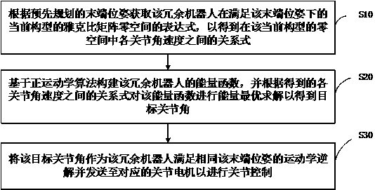
[0055] Please refer to image 3 , this embodiment proposes a redundant robot inverse kinematics solution method, combining the redundant robot's null space and using energy as a criterion, it can well improve the shortcomings of the inverse kinematics solution method in the prior art.

[0056] Such as image 3 As shown, the redundant robot inverse kinematics solution method mainly includes the following steps:

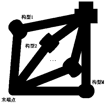
[0057] Step S10, according to the pre-planned end pose, obtain the expression of the null space of the Jacobian matrix of the redundant robot in the current configuration satisfying the end pose, so as to obtain the angular velocity of each joint in the null space of the current configuration relationship between.

[0058] After a desired end pose of the redundant robot is given, a set of joint angles is obtained by using inverse kinematics solution and sent to the joint motors for joint control, so that the redundant robot performs the corresponding motion. In this...

Embodiment 2

[0082] Please refer to image 3 , based on the method of the above-mentioned embodiment 1, this embodiment proposes a redundant robot inverse kinematics solution method, for the energy function of the redundant robot constructed based on the forward kinematics algorithm in the above step S20, exemplary, the energy function It may include but not limited to gravitational potential energy function, gravity compensation function, repulsion potential energy function, etc. Specifically, the energy function can be constructed according to actual needs.

[0083] In one embodiment, since each joint is subjected to the action of gravity during space movement, gravitational potential energy will be generated. Exemplarily, the energy function is a gravitational potential energy function. For the construction of the gravitational potential energy function, such as Figure 5 As shown, it mainly includes the following sub-steps:

[0084] In sub-step S210, the coordinate system pose of ea...

Embodiment 3

[0103] Please refer to Figure 6 , based on the method of the above-mentioned embodiment 1, this embodiment proposes a redundant robot inverse kinematics solving device 10, including:

[0104] The null space solving module 100 is used to obtain the expression of the null space of the Jacobian matrix of the redundant robot in the current configuration satisfying the terminal pose according to the pre-planned terminal pose, so as to obtain the expression of the null space of the Jacobian matrix in the current configuration The relationship between the angular velocities of each joint in the null space of .

[0105] The energy function construction module 200 is used to construct the energy function of the redundant robot based on the forward kinematics algorithm, and perform an energy optimal solution to the energy function according to the relationship between the angular velocities of the joints to obtain the target joint angle .

[0106] The kinematics inverse solution acqu...


PUM


Abstract

The embodiment of the invention discloses a redundant robot inverse kinematics solving method and device and a redundant robot. The method comprises the steps of obtaining an expression of a Jacobianmatrix null space, meeting a tail end pose, of the redundant robot under a current configuration according to the pre-planned tail end pose, so as to obtain a relational expression among angular velocities of joints in the null space of the current configuration; and constructing an energy function of the redundant robot based on a positive kinematics algorithm, carrying out energy optimal solution on the energy function according to a relational expression between joint angular velocities to obtain a target joint angle, taking the target joint angle as a kinematics inverse solution meeting the tail end pose, and sending the kinematics inverse solution to a corresponding joint motor. According to the technical scheme, redundant robot inverse kinematics is optimally solved based on energy,the joint angle kinematics inverse solution obtained through calculation of the method conforms to organism characteristics and is visual in understanding, and when a tail end track passes through different quadrants, all joint angles can be kept continuous and smooth.

Description

technical field [0001] The invention relates to the technical field of redundant robots, in particular to a redundant robot inverse kinematics solution method, device and redundant robot. Background technique [0002] Redundant robot inverse kinematics refers to the process of given a planned robot end pose, using inverse kinematics algorithm to solve a set of joint angles and sending them to the motors of each joint for motion control. Since the inverse kinematics of redundant robots has the characteristics of infinite solutions, how to efficiently solve it has become a problem of widespread concern. [0003] At present, the solutions for inverse kinematics can be generally divided into two categories, namely analytical methods and numerical iterative methods. For analytical inverse kinematics, using the geometric characteristics of the robot to solve each joint angle usually requires adding some additional geometric constraints to solve, such as specifying the angle of th...

Claims


Application Information

Patent Timeline
Patent Type & Authority Applications(China)
IPC IPC(8): G06F17/15G06F17/16G06F30/20G06F119/14
CPCG06F17/15G06F17/16G06F30/20G06F2119/14B25J9/1607B25J9/1643G05B2219/40367G05B2219/39361G06F17/11G05B2219/50391
Inventor 王岳嵩黄荔群任晓雨赵明国熊友军
Owner UBTECH ROBOTICS CORP LTD
Learn More