Hydraulic torque converter

A technology of hydraulic torque converter and force shaft, applied in the field of large-tonnage torque converter, can solve the problems of oil leakage, limited space, loosening and other problems at the joint, so as to reduce the risk of oil leakage, reduce the difficulty of assembly, and improve the assembly The effect of efficiency

Pending Publication Date: 2020-08-14
XUZHOU XCMG DRIVELINE TECH CO LTD
View PDF0 Cites 0 Cited by
  • Summary
  • Abstract
  • Description
  • Claims
  • Application Information

AI Technical Summary

Problems solved by technology

The existing large-tonnage hydraulic torque converter cannot take into account the traction power performance of the complete machine at a certain speed between 1850-2050 rpm, and has defects such as high fuel consumption and low vehicle speed
The main reasons affecting its performance include the following points: 1. The connecting shaft of the cover wheel and the output shaft head are connected by bolts, and there is a possibility of loosening; 2. Oil leakage at the joint between the offset small box and the large box Problem; 3. The space between the offset small box and the large box and the middle section is limited, and there is no installation space for the free guide wheel. Moreover, the current product torque converter movement assembly and the large box have limited space and cannot be installed. Locking mechanism, it is difficult to upgrade and optimize the torque converter

Method used


Image

  • Hydraulic torque converter
  • Hydraulic torque converter
  • Hydraulic torque converter

Examples


Embodiment Construction

[0021] In order to make the object, technical solution and advantages of the present invention more clear, the present invention will be further described in detail below in conjunction with the examples. It should be understood that the specific embodiments described here are only used to explain the present invention, not to limit the present invention.

[0022] The application principle of the present invention will be described in detail below in conjunction with the accompanying drawings.

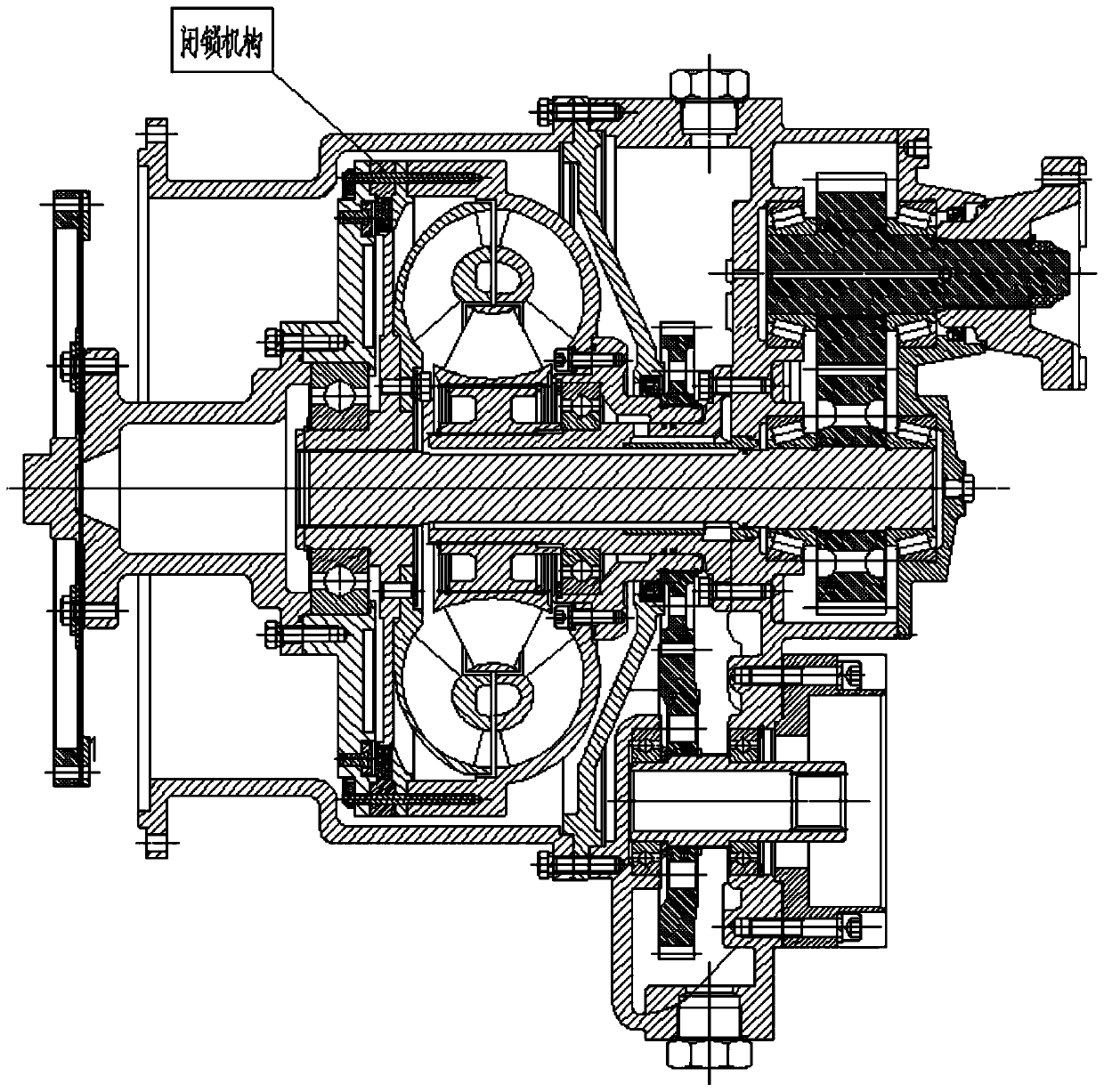
[0023] As shown in the figure, the specific process of assembling the torque converter of the present invention is as follows:

[0024] Part 1: Assembling the movement assembly

[0025] Step 1: Install the deep groove ball bearing 6218 2_18 into the bearing seat hole of the pump wheel mounting base 2_17, and install the shaft retaining ring B 2_22, and then install the O-ring B 2_16 to the clamp of the pump wheel mounting base 2_17 In the groove, finally connect with the pump wheel 2...


PUM


Abstract

The invention discloses a hydraulic torque converter. The hydraulic torque converter comprises a box body, a movement assembly, an oil insulating plate, an output shaft, a turbine shaft and a power take-off shaft. The movement assembly, the oil insulating plate and the box body are sequentially assembled in the axial length direction of the turbine shaft, the box body is formed by a large box bodyand a biasing small box body cast integrally, the oil insulating plate is located between the movement assembly and the large box body, and the power take-off shaft and the output shaft are assembledon one side of the biasing small box body and located on the two sides of the turbine shaft correspondingly. A matching adaptation technology in which the same torque converter is compatible with different rated rotating speeds can be achieved, and the requirements for the whole machine traction power performance at different rotating speeds can be met.

Description

technical field [0001] The invention belongs to the field of large-tonnage torque converters, and in particular relates to a hydraulic torque converter. Background technique [0002] In the prior art, the large-tonnage hydraulic torque converter is one of the core components of large-scale construction machinery, and its comprehensive performance determines the life of the complete machine. The existing large-tonnage hydraulic torque converter cannot take into account the traction power performance of the complete machine at a certain speed between 1850 and 2050 rpm, and has defects such as high fuel consumption and low vehicle speed. The main reasons affecting its performance include the following points: 1. The connecting shaft of the cover wheel and the output shaft head are connected by bolts, and there is a possibility of loosening; 2. Oil leakage at the joint between the offset small box and the large box Problem; 3. The space between the offset small box and the larg...

Claims


Application Information

Patent Timeline
Patent Type & Authority Applications(China)
IPC IPC(8): F16H45/02F16H41/04F16H41/24
CPCF16H41/04F16H41/24F16H45/02F16H2045/0294
Inventor 龚虎蒋立俏徐东云吴秀翠龚滏生
Owner XUZHOU XCMG DRIVELINE TECH CO LTD
Why Eureka
Try Eureka