UV curing machine and UV lamp box thereof

A curing machine and light box technology, applied in printing machines, general parts of printing machinery, printing and other directions, can solve the problems of affecting the curing effect, affecting the service life of the UV lamp, and the heat dissipation effect of the reflector is not ideal, so as to improve the reflection of UV energy. rate, the effect of improving the curing effect

Active Publication Date: 2020-08-14
东莞市汇创智能装备有限公司
View PDF15 Cites 8 Cited by
  • Summary
  • Abstract
  • Description
  • Claims
  • Application Information

AI Technical Summary

Problems solved by technology

With this heat dissipation structure, only the side surface of the reflector away from the UV lamp is blown by the wind, and the heat dissipation effect of the reflector itself is not ideal, and the UV lamp and the product to be cured are blocked by the reflector and cannot be blown by the wind. The heat of the UV lamp is also easy to accumulate and cause the temperature of the UV lamp to be too high, which will affect the service life of the UV lamp, and the high temperature of the product to be cured will also affect the curing effect

Method used


Image

  • UV curing machine and UV lamp box thereof
  • UV curing machine and UV lamp box thereof
  • UV curing machine and UV lamp box thereof

Examples


Embodiment Construction

[0021] The present invention will be described in further detail below in conjunction with the accompanying drawings and specific embodiments. It should be understood that the following exemplary embodiments and descriptions are only used to explain the present invention, not as a limitation to the present invention, and, in the case of no conflict, the embodiments in the present invention and the features in the embodiments can be combined with each other .

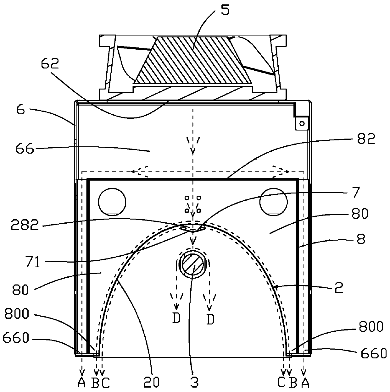
[0022] Such as Figure 1 to Figure 3 As shown, a UV light box 1 of a UV curing machine provided by an optional embodiment of the present invention includes a reflector 2 with an arc shape and an inner arc as the reflective surface 20, and a reflective surface arranged on the reflector 2 The UV lamp 3 on one side of 20 and the fan 5 arranged on the outer arc surface 22 side of the reflector 2, the arc top of the reflector 2 is provided with a through hole 24 penetrating the reflector 2, the The UV light box also include...


PUM


Abstract

The embodiment of the invention relates to a UV curing machine and a UV lamp box thereof. The UV lamp box comprises a reflector, a UV lamp, a fan and an air deflector, wherein the reflector is in a cambered surface shape, the inner cambered surface of the reflector serves as a reflecting surface, the UV lamp is arranged on one side of the reflecting surface of the reflector, the fan is arranged onone side of the outer cambered surface of the reflector, the air deflector is arranged at the position, close to the camber top of the reflector, between the reflector and the UV lamp and extends inthe length direction of the reflector, through holes are formed in the camber top of the reflector, the air deflector directly faces the through holes, and the width of the air deflector is larger than the sizes of the through holes in the width direction of the air deflector. According to the UV lamp box, high-speed air flow blown out by the fan is blown to the camber top of the outer cambered surface of the reflector and flows towards the two sides along the outer cambered surface, part of the air flow further passes through the through holes to be blown to the air deflector, then is blown to the reflecting surface of the reflector under the guidance of the air deflector and flows along the reflecting surface, and the inner side and the outer side of the reflector are blown and thermallydissipated, so that the reflectivity of UV energy is improved favorably, and the air flow flowing along the reflecting surface is finally blown to a product to be cured for air-cooling and thermal dissipation, so that the curing effect is improved favorably.

Description

technical field [0001] The embodiment of the present invention relates to the field of UV curing technology, in particular to a UV curing machine and its UV light box. Background technique [0002] The UV curing machine uses a UV light box (for example: LED-UV lamp) to cure UV ink, UV glue, UV coating, etc., and is widely used in many fields such as communications, electronics, optics, and printing. The UV lamp and other components inside the UV light box generate a lot of heat when they work, and the higher the temperature of the reflector, the lower its UV energy reflection ability. In actual production, it is necessary to dissipate heat from the UV lamp in time. [0003] A kind of existing UV curing machine, the UV lamp box that it adopts comprises UV lamp, and described UV lamp one side is provided with reflective plate, and reflective plate is used for also reflecting the UV energy that UV lamp emits toward the direction away from the product to be cured to the product ...

Claims


Application Information

Patent Timeline
Patent Type & Authority Applications(China)
IPC IPC(8): B41F23/04B05D3/06B05D3/04
CPCB41F23/0483B41F23/0409B41F23/0453B05D3/067B05D3/0426
Inventor 刘情
Owner 东莞市汇创智能装备有限公司
Why Eureka
Try Eureka