
Vision-based multi-industrial-robot fault detection method and system

An industrial robot, fault detection technology, applied in manipulators, manufacturing tools, program-controlled manipulators, etc., can solve the problems of high cost and complex detection process, and achieve the effect of low cost and simple and accurate detection process

Active Publication Date: 2020-08-14
WUHAN INSTITUTE OF TECHNOLOGY
View PDF7 Cites 3 Cited by
  • Summary
  • Abstract
  • Description
  • Claims
  • Application Information

AI Technical Summary

Problems solved by technology

[0009]In the prior art, it is necessary to use multiple data acquisition devices to collect the state information of industrial robots, and process the state information collected by multiple data acquisition devices to judge the industrial Whether the state of the robot is abnormal, the detection process is more complicated and the cost is higher

Method used


Image

  • Vision-based multi-industrial-robot fault detection method and system
  • Vision-based multi-industrial-robot fault detection method and system
  • Vision-based multi-industrial-robot fault detection method and system

Examples


Embodiment 1

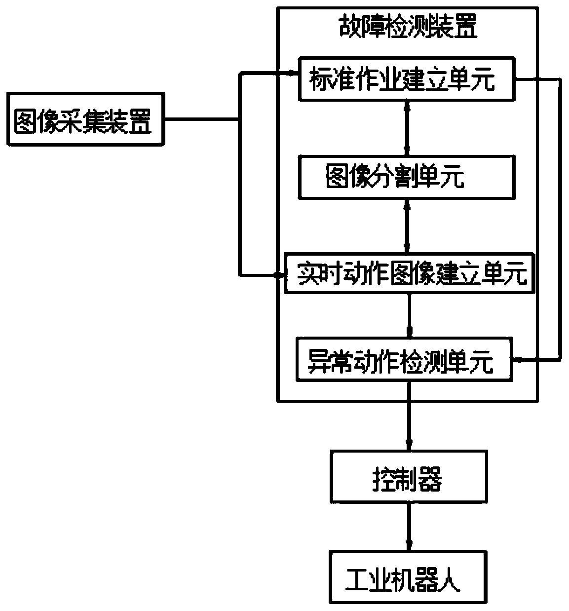
[0072] refer to figure 1 , a vision-based multi-industrial robot fault detection system, including an image acquisition device, a fault detection device and a controller.

[0073] Each part will be described in detail below in turn.

[0074] The image acquisition device is used to collect standard operation videos of multi-industrial robots, and is also used to collect real-time action videos of multi-industrial robots in real time. It is worth noting that, in this embodiment, the image acquisition device is a high-definition camera.

[0075] The fault detection device is used to receive the multi-industrial robot standard operation video collected by the image acquisition device and establish a plurality of single-industrial robot standard operation mode video frame sequences A13, 11 , I 12 ,…I 1m >, also be used for receiving the multi-industrial robot real-time action video that image acquisition device collects in real time, set up a plurality of single industrial robot...

Embodiment 2

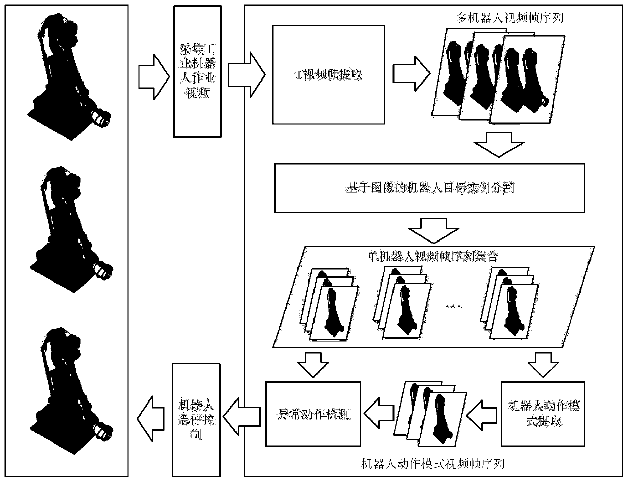
[0114] refer to figure 2 , 6 , a vision-based multi-industrial robot fault detection method, including the following steps,

[0115] S1: collect the standard operation video of multiple industrial robots, establish the video frame sequence A13 of multiple single industrial robot standard operation modes, , execute S2;

[0116] S2: Collect multi-industrial robot operation videos in real time, and create multiple single-industrial robot real-time operation video frame sequences A22, . The single-industrial robot real-time operation video frame sequence A22 includes multiple frames of single-industrial robot real-time Action image, execute S3;

[0117] S3: Match the real-time motion image of the single industrial robot with the image in the corresponding single industrial robot standard operating mode video frame sequence A13, and use the two-stage method to detect whether the single industrial robot is abnormal. If yes, execute S4, if not, execute S2 ;

[0118] S4: Control ...


PUM


Abstract

The invention provides a vision-based multi-industrial-robot fault detection method and system. The vision-based multi-industrial-robot fault detection method comprises the following steps of S1, collecting a multi-industrial-robot standard operation video, establishing multiple single-industrial-robot standard operation mode video frame sequences A13, and executing S2; S2, acquiring a multi-industrial-robot operation video in real time, establishing multiple single-industrial-robot real-time operation video frame sequences A22, and executing S3; S3, matching a single-industrial-robot real-time action image with an image in a corresponding single-industrial-robot standard operation mode video frame sequence A13, detecting whether the single industrial robot acts abnormally or not by adopting a two-stage method, if so, executing S4, and if not, executing S2; and S4, controlling the industrial robot to stop suddenly. The method and the system have the advantages that sudden faults of anindustrial robot body are found in a non-contact mode, so that the safety accident that the robot hurts people during man-machine cooperation is avoided, and the detection process is simple and accurate.

Description

technical field [0001] The invention relates to the technical field of intelligent manufacturing, in particular to a vision-based multi-industrial robot fault detection method and system. Background technique [0002] Industrial robot is a complex system composed of automation, machinery, embedded, hydraulic, electrical and other hardware and its control software. It can replace workers in some dangerous and complicated repetitive labor. Industrial robots have been widely used in the manufacturing industry due to their high precision and no need for rest. However, with the extensive application of industrial robots, incidents of industrial robots hurting people happen from time to time. The main causes of industrial robot safety accidents are human factors and the failure of the robot itself. Among them, the safety accidents caused by the robot's own misoperation accounted for more than half of the proportion. Human factors can be controlled through enhanced management a...

Claims


Application Information

Patent Timeline
IPC IPC(8): B25J19/00B25J9/16
CPCB25J19/0095B25J9/1692
Inventor 陈灯彭煜祺魏巍张彦铎吴云韬周华兵刘玮段功豪于宝成卢涛鞠剑平唐剑影徐文霞彭丽杨艺晨王逸文
Owner WUHAN INSTITUTE OF TECHNOLOGY
Learn More