
Automatic spraying device

An automatic spraying and heating device technology, applied in spraying devices, devices for coating liquid on the surface, coatings, etc., can solve the problem that the uneven spraying of the catalyst layer affects the structure and physical and chemical properties of the membrane electrode catalyst layer, and affects the membrane electrode fuel cell. Performance, cannot effectively solve the problem of membrane swelling, etc., to achieve the effect of uniform force, improve quality, and reduce waste

Inactive Publication Date: 2020-08-14
GREE ELECTRIC APPLIANCES INC
View PDF12 Cites 1 Cited by
  • Summary
  • Abstract
  • Description
  • Claims
  • Application Information

AI Technical Summary

Problems solved by technology

The existing automatic spraying device lacks a heating device for effectively heating the solvent sprayed from the spraying device, which makes it difficult for the solvent in the catalyst slurry to dissolve when the liquid catalyst, especially the catalyst containing a less volatile solvent, is sprayed on the membrane. Rapid volatilization, cannot effectively solve the swelling problem of the membrane
[0007] In the prior art, the automatic spraying device also has the problem that the spray coating liquid is stored in the spray gun or the hopper for storing the spray coating liquid for too long, which will easily cause the spray coating liquid, especially the catalyst slurry, to accumulate and precipitate, and easily cause the catalyst layer in the spraying process to be unevenly sprayed. It affects the structure and physical and chemical properties of the membrane electrode catalyst layer, and ultimately affects the performance of the membrane electrode and the fuel cell to which it is applied

Method used


Image

  • Automatic spraying device
  • Automatic spraying device
  • Automatic spraying device

Examples


Embodiment 1

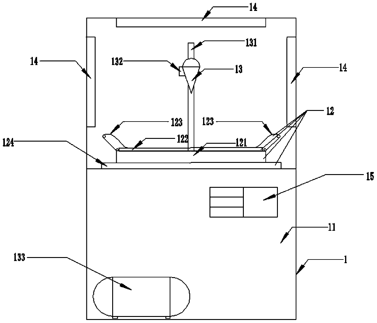
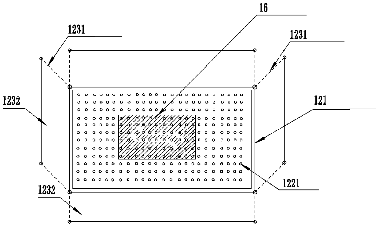
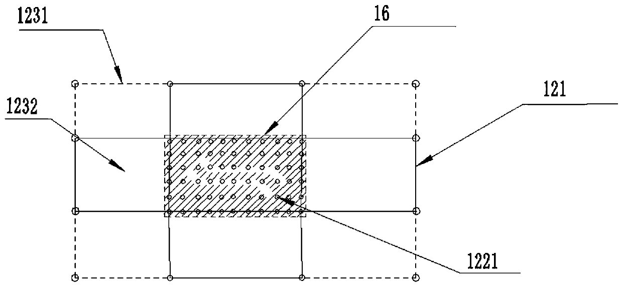
[0036] This embodiment discloses an automatic spraying device 1, which includes: a heating box 11 provided with a heating device, a spraying operation cavity is formed in the heating box 11, and when the automatic spraying device 1 is in operation, the heating device in the heating box The spraying operation cavity is heated; the spraying operation cavity is provided with a spray gun 13 and a workbench 12 for fixing the workpiece to be sprayed. When the workpiece to be sprayed is fixed on the workbench 12, the spray gun 13 sprays the spray material to the workpiece to be sprayed superior.

[0037] Further, the workpiece to be sprayed is a proton exchange membrane, and the sprayed material is a catalyst slurry.

[0038] Further, the heating device includes an infrared heating device 14, and when the automatic spraying device is working, the infrared heating device 14 keeps the temperature in the spraying cavity within a preset temperature range. Infrared heating device 14 incl...


PUM


Abstract

The invention relates to an automatic spraying device. The automatic spraying device comprises a heating box body provided with a heating device, a spraying operation cavity is formed in the heating box body, and when the automatic spraying device works, the heating device in the heating box body heats the spraying operation cavity. A spray gun and a workbench which is used for fixing a to-be-sprayed workpiece are arranged in the spraying operation cavity, and when the to-be-sprayed workpiece is fixed to the workbench, the spray gun sprays a spraying material to the to-be-sprayed workpiece. During spraying operation, a heating box is arranged, so that the temperature of the spraying operation cavity, namely the temperature of the spraying environment, can be maintained in a preset high range during operation of the automatic spraying device, the consistency of the temperature of the spraying environment is guaranteed, the waste amount of the spraying material is reduced, the problem that the solvent volatilization speed of the spraying material is low is solved well, the problem of swelling of a proton exchange membrane caused by long contact time of a solvent and the sprayed workpiece, particularly the proton exchange membrane, is solved, and the quality of the sprayed workpiece, particularly a membrane electrode, is greatly improved.

Description

technical field [0001] The invention relates to an automatic spraying device, which belongs to the technical field of automatic spraying equipment. Background technique [0002] In the field of automatic spraying technology, it is often required that the spraying material sprayed on the workpiece to be sprayed requires rapid volatilization to ensure that the spraying material can be attached to the sprayed workpiece with high quality and uniformity while preventing the long-term contact between the solvent and the sprayed workpiece from affecting the shape of the sprayed workpiece. And adverse effects such as swelling, corrosion, deformation, etc. caused by the structure, especially when spraying on the membrane material, it is even more required that the spraying material can be sprayed on the membrane material for rapid volatilization to avoid swelling of the membrane material. [0003] As an emerging clean energy with development prospects, hydrogen energy belongs to the ...

Claims


Application Information

Patent Timeline
Patent Type & Authority Applications(China)
IPC IPC(8): B05B16/20B05D3/02B05B13/02B05B12/00B05B12/08B05B12/10B05B13/04B05B15/20B05B15/62
CPCB05B12/00B05B12/085B05B12/10B05B13/0285B05B13/0421B05D3/0227B05D3/0263B05B15/20B05B15/62B05B16/20
Inventor 苏琳陈晓唐稚阳刘智亮
Owner GREE ELECTRIC APPLIANCES INC
Learn More