Storage box for earphones

A technology for storage boxes and earphones, which is applied in the field of storage, and can solve problems such as traces, large shell impact, and inconvenient use

Pending Publication Date: 2020-08-11
KUNSHAN KERSEN SCI & TECH
View PDF0 Cites 0 Cited by
  • Summary
  • Abstract
  • Description
  • Claims
  • Application Information

AI Technical Summary

Problems solved by technology

However, the current charging box cannot be opened automatically, and requires both hands to open it, which is inconvenient to use. In addition, the opening speed is relatively fast, and the impact on the shell at the stop position is very large, and there will be marks or paint peeling after a long-term impact risk, poor user experience

Method used


Image

  • Storage box for earphones
  • Storage box for earphones
  • Storage box for earphones

Examples


Embodiment 1

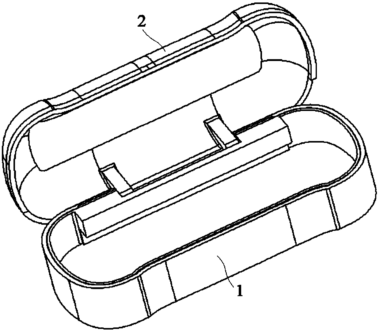
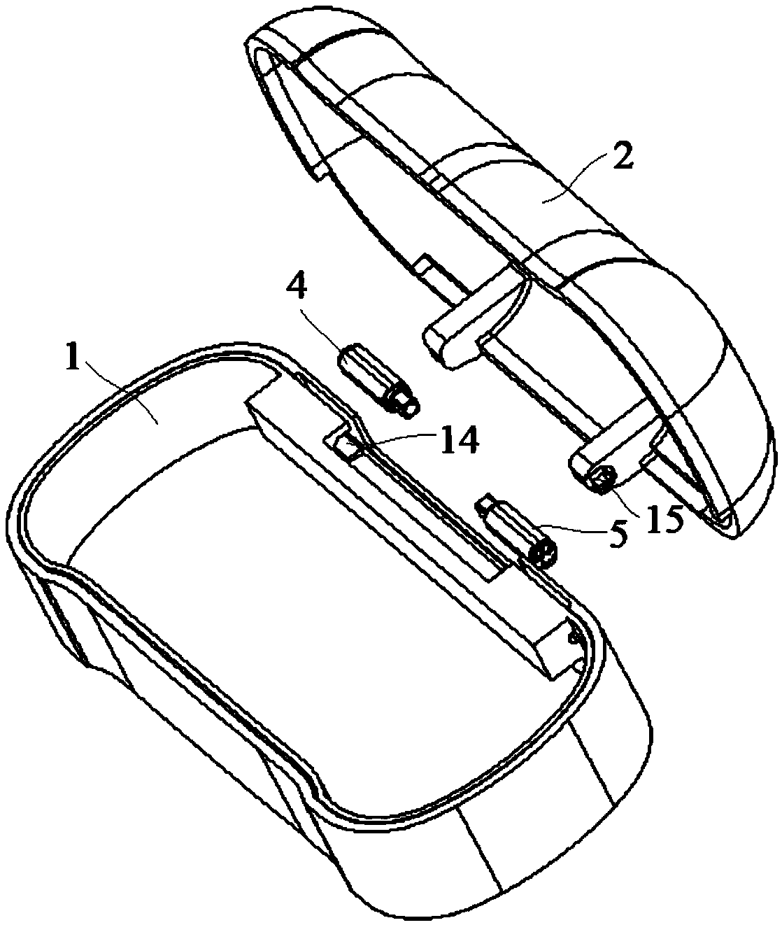
[0028] Embodiment 1: A storage box for earphones, including a box body 1 and a cover body 2, the cover body 2 is rotatably connected to the box body 1 through a rotating shaft mechanism, and the rotating shaft mechanism includes a power rotating shaft 4 and a resistance Rotating shaft 5, one end of the power rotating shaft 4 is connected with the cover body 2, and is used to drive the cover body 2 to rotate, and one end of the resistance rotating shaft 5 is connected with the cover body 2, and rotates under the drive of the cover body 2;

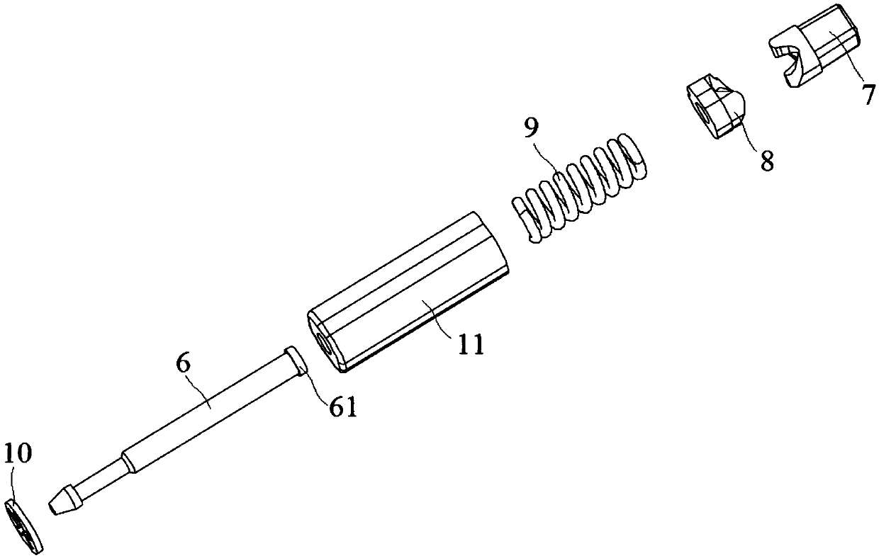
[0029] The power rotating shaft 4 further includes a shaft core 6 and a rotating cam 7, a sliding cam 8, and an elastic assembly 9 which are successively sleeved on the shaft core 6. The cam surface of the rotating cam 7 cooperates with the cam surface of the sliding cam 8. The elastic component 9 is located between the sliding cam 8 and the stopper at one end of the shaft core 6, and the sliding cam 8 can slide axially along the shaft core 6...

Embodiment 2

[0033] Embodiment 2: A storage box for earphones, including a box body 1 and a cover body 2, the cover body 2 is rotatably connected to the box body 1 through a rotating shaft mechanism, and the rotating shaft mechanism includes a power rotating shaft 4 and a resistance Rotating shaft 5, one end of the power rotating shaft 4 is connected with the cover body 2, and is used to drive the cover body 2 to rotate, and one end of the resistance rotating shaft 5 is connected with the cover body 2, and rotates under the drive of the cover body 2;

[0034]The power rotating shaft 4 further includes a shaft core 6 and a rotating cam 7, a sliding cam 8, and an elastic assembly 9 which are successively sleeved on the shaft core 6. The cam surface of the rotating cam 7 cooperates with the cam surface of the sliding cam 8. The elastic component 9 is located between the sliding cam 8 and the stopper at one end of the shaft core 6, and the sliding cam 8 can slide axially along the shaft core 6 ...


PUM


Abstract

The invention discloses a storage box for earphones. The box comprises a box body and a cover body, the cover body is rotatably connected with the box body through a rotating shaft mechanism; the rotating shaft mechanism comprises a power rotating shaft and a resistance rotating shaft; one end of the power rotating shaft is connected with the cover body to drive rotation of the cover body, one endof the resistance rotating shaft is connected with the cover body, and the resistance rotating shaft rotates under the driving of the cover body, the power rotating shaft further comprises a shaft core, and a rotating cam, a sliding cam and an elastic assembly which are sleeved on the shaft core in order, the resistance rotating shaft further comprises a core rod, and a rotating shaft sleeve, a sliding shaft sleeve and an elastic element which are sleeved on the core rod in order, two protruding points are arranged on the end face of the rotating shaft sleeve, and two arc-shaped grooves allowing the protruding points to be embedded therein are formed in the end face of the sliding shaft sleeve. According to the invention, the protruding points completely stop after entering the third groove and do not tend to climb upwards any more, i.e., the cover body completely stops and does not shake at all, so that the hand is not bounced, and the user experience is good.

Description

technical field [0001] The invention relates to a storage box for earphones, which belongs to the technical field of storage. Background technique [0002] With the development of wireless network and chip technology, more and more wireless products appear in our life. For example, the emergence of wireless earphones has made it easier for people to make and receive calls and listen to music. The design and use of wireless earphones are inseparable from the charging box. The charging box is designed to charge the earphones on the one hand, and also to connect the earphones and update the software on the other hand. However, the current charging box cannot be opened automatically, and requires both hands to open it, which is inconvenient to use. In addition, the opening speed is relatively fast, and the impact on the shell at the stop position is very large, and there will be marks or paint peeling after a long-term impact Risk, poor user experience. Contents of the inven...

Claims


Application Information

Patent Timeline
IPC IPC(8): H04R1/10
CPCH04R1/10H04R2201/10
Inventor 董小慧瞿李平
Owner KUNSHAN KERSEN SCI & TECH
Why Eureka
Try Eureka