
Electricity Roll magnetic DC synchronous generator does not control the rectification capacitance energy outer ring control method

A DC synchronous and generator technology, applied in the direction of controlling generators through magnetic field changes, can solve the problems of slow dynamic adjustment, difficult to select control parameters, large dynamic voltage fluctuations, etc., to achieve dynamic performance optimization, and overcome the difficulty of parameter tuning. Effect

Active Publication Date: 2021-06-25
NANJING UNIV OF AERONAUTICS & ASTRONAUTICS
View PDF7 Cites 0 Cited by
  • Summary
  • Abstract
  • Description
  • Claims
  • Application Information

AI Technical Summary

Problems solved by technology

[0005] Second, the electrical equipment in the aviation power supply system often has violent sudden loading and unloading actions, resulting in severe voltage fluctuations
[0006] Third, the speed range of the aero-generator is large, which causes the parameters of the motor to change at different speeds, making it difficult to select control parameters suitable for the entire speed range
[0007] The special working conditions of the aeronautical excitation DC synchronous generator make the control of the generator more difficult, resulting in a longer dynamic adjustment time, larger voltage fluctuations during dynamic adjustment, and deterioration of the control effect when the speed changes.
[0008] In the existing technology, the control method for the electric excitation DC synchronous generator has the disadvantages of slow dynamic adjustment speed, large dynamic voltage fluctuation, and poor adaptability to speed changes, which cannot meet the dynamic characteristics of the electric excitation DC synchronous generator in the aviation power supply system. requirements and wide speed range requirements

Method used


Image

  • Electricity Roll magnetic DC synchronous generator does not control the rectification capacitance energy outer ring control method
  • Electricity Roll magnetic DC synchronous generator does not control the rectification capacitance energy outer ring control method
  • Electricity Roll magnetic DC synchronous generator does not control the rectification capacitance energy outer ring control method

Examples


Embodiment

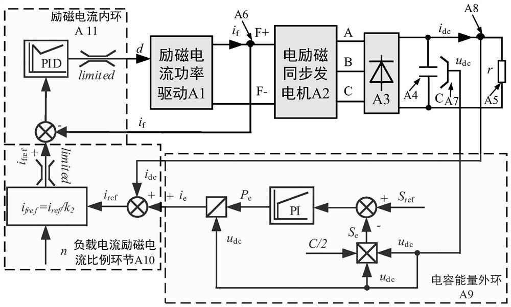
[0035] An embodiment of the present invention provides an outer loop control method for an uncontrolled rectification capacitor energy of an electrically excited DC synchronous generator. Among them, the principle block diagram of the outer loop control method of the uncontrolled rectification capacitor energy of the electrically excited DC synchronous generator is shown in figure 1 As shown, including excitation current power drive A1, electric excitation synchronous generator A2, uncontrolled rectifier A3, DC side filter capacitor A4, DC load A5, excitation current sensor A6, DC side output voltage sensor A7, DC side output current sensor A8 , Capacitive energy outer ring A9, load current excitation current ratio counter-offer A10 and excitation current inner ring A11. figure 1 The parameter i in f represents the excitation current of the generator, i dc Represents the output current of the DC side of the generator, u dc Represents the output voltage of the DC side of the...


PUM


Abstract

The invention discloses an outer loop control method of an electric excitation DC synchronous generator without controlling the energy of rectification capacitor, which uses the energy storage link of filter capacitor on the DC side of a rectifier bridge, and realizes the indirect control of DC side voltage by feeding back capacitor energy state information . On the basis of taking into account the speed and load, the proportional link between the output current and the excitation current is introduced to realize the parameter adaptation of the generator under different working conditions. The present invention includes capacitive energy outer-loop control with uncontrolled rectifier bridge filter capacitor storage energy as the adjustment object; proportional links for solving the relationship between output current and excitation current under different working conditions; excitation current inner-loop control with excitation current as the adjustment object . The invention can realize the stable control of the DC output voltage of the synchronous generator, accelerate the dynamic adjustment process when the DC side load of the generator changes, has strong adaptability to different working conditions, and can maintain the relative stability of the DC side output voltage. Enhance the dynamic performance of the power supply system.

Description

technical field [0001] The invention relates to a control method for an uncontrolled rectification capacitor energy outer loop of an electrically excited DC synchronous generator, which belongs to the technical field of electrical control. Background technique [0002] The electric excitation DC synchronous generator contains the armature winding and the field winding. The output control of the generator can be realized by adjusting the excitation current of the excitation winding. The armature winding is rectified by an uncontrolled rectifier to output a DC voltage. Because the electrically excited DC synchronous generator has outstanding advantages such as simple structure, high reliability, low cost, and easy fault de-excitation, it is especially suitable for applications in high-speed and harsh environments such as aviation power supplies. [0003] The generator is the core component of the aviation power supply system, and the aviation power supply system has high req...

Claims


Application Information

Patent Timeline
Patent Type & Authority Patents(China)
IPC IPC(8): H02P9/38
CPCH02P9/38
Inventor 张卓然许彦武卞张铭于立
Owner NANJING UNIV OF AERONAUTICS & ASTRONAUTICS
Learn More