
Satisfaction optimization prediction fault-tolerant control method for double-three-level inverter

A three-level inverter, fault-tolerant control technology, applied in electrical components, AC power input to DC power output, output power conversion devices, etc., can solve the problem of small number of redundant switch states, weak topology fault tolerance, Increase equipment volume and other issues to achieve the effect of strong fault tolerance, strong operability, and low harmonic distortion rate

Inactive Publication Date: 2020-08-11
JIANGSU OCEAN UNIV
View PDF0 Cites 1 Cited by
  • Summary
  • Abstract
  • Description
  • Claims
  • Application Information

AI Technical Summary

Problems solved by technology

[0002] The design of the fault-tolerant control method of the power converter in the prior art mainly includes parallel redundant phases, which usually adopts a cold standby mode, that is, during normal operation, the redundant bridge arm will not be switched to run, but in When an open-circuit fault occurs, the faulty bridge arm is replaced, and the fault-tolerant measures of parallel redundant phases increase the size of the equipment and increase additional costs. At the same time, it may be necessary to increase the external drive circuit, making the control more complicated;
[0003] Another solution is to use the fault-tolerant capability of the topology itself. The modularity of the traditional topology H-bridge fully exerts its redundant fault-tolerant capability. It cuts off the full-bridge power units in the same position of the three phases at the same time when an open circuit fault occurs, so that 7 The phase voltage output level of the level H bridge cascaded topology will be reduced to 5 levels, but the traditional topology itself has weak fault tolerance, and the number of redundant switch states is small, and the health of the fault will be the same as the full bridge power at the same position Unnecessary overhead due to fault-tolerant approach to cell removal;

Method used


Image

  • Satisfaction optimization prediction fault-tolerant control method for double-three-level inverter
  • Satisfaction optimization prediction fault-tolerant control method for double-three-level inverter
  • Satisfaction optimization prediction fault-tolerant control method for double-three-level inverter

Examples


Embodiment 1

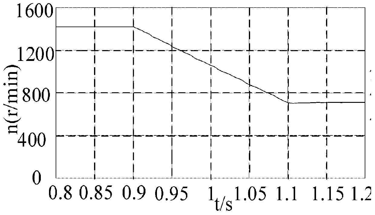
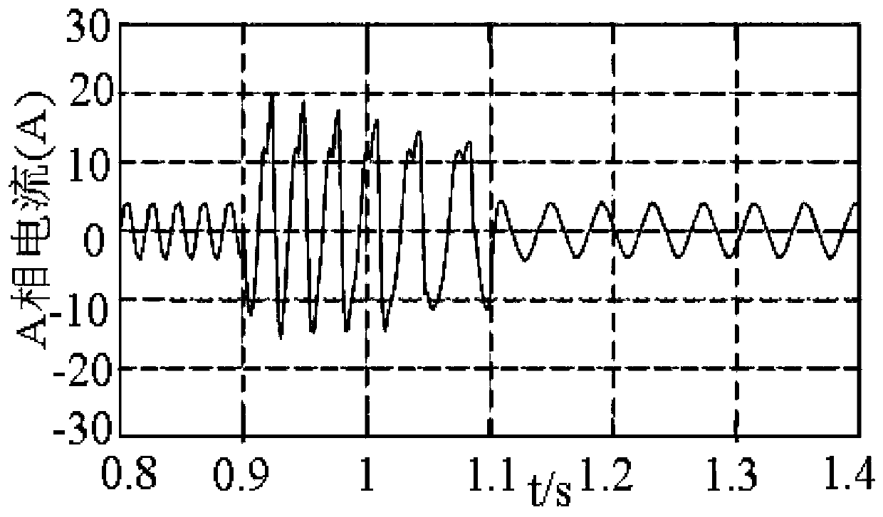
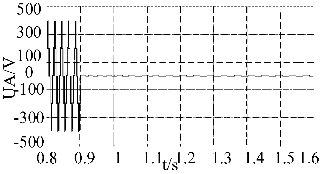
[0047] Embodiment 1, with reference to figure 1 —10, a kind of dual three-level inverter satisfaction optimization predictive fault-tolerant control method, its steps are,

[0048] (1) Open the stator winding of the motor, and the two ends of the stator winding are powered by two identical inverters, and the two inverters share the same set of DC bus to form a common bus dual three-level topology;

[0049] (2) When an open-circuit fault occurs in a switching device, the maximum output voltage of the inverter drops to half of the original value, and the range of voltage jumps controlled by the inverter is set within Vdc / 2. The available switching states of the inner hexagon of the flat topology synthesize the reference voltage vector;

[0050] (3) Taking the current following performance as the main control target of the dual-inverter system and establishing a three-phase current satisfactory error function to optimize the aforementioned reference voltage vector;

[0051] (4)...

Embodiment 2

[0063] Embodiment 2, a kind of satisfactory optimal predictive fault-tolerant control method for dual three-level inverters described in Embodiment 1, in order to perform satisfactory optimal fault-tolerant control by operating dual three-level inverters through the MPC controller, assuming w(k) =w(k+1), establish the dynamic mathematical model of the open-winding asynchronous motor with the stator current and the rotor flux linkage as the state variables under the two-phase stationary coordinate system,

[0064]

[0065] In the formula: i sα ,i sβ Respectively, the stator current α, β components in the coordinate system (A); λ rα ,λ rβ Respectively, the component (A) of the rotor flux linkage α and β coordinate system; u sα ,u sβ Respectively, the stator voltage α, β components in the coordinate system (V); L m is the mutual inductance (H); T r =L r / R r , is the rotor electromagnetic time constant; k r =L m / L r ,r o =R s +R r k r 2 ,δ=1-L m 2 / L s / L ...

Embodiment 3

[0071] Embodiment 3, a kind of dual three-level inverter satisfactory optimization prediction fault-tolerant control method described in Embodiment 2, the described three-phase current satisfaction error function is the following formula:

[0072]

[0073] Where: Δi=i * -i(k+1); δ is the maximum allowable ring width of current following;

[0074] The figure below is the judgment diagram of current following satisfaction. The present invention sets [0, δ] as the satisfactory interval. When the current following deviation |Δi| is within this interval, u i = 0, indicating that the current following has achieved a satisfactory effect, when the current following deviation exceeds this range, u i =1, indicating that its following performance is not good, the attached picture Figure 9 It is the judgment diagram of current following satisfaction.


PUM


Abstract

The invention discloses a satisfaction optimization prediction fault-tolerant control method for a double-three-level inverter. A stator winding of the motor is opened; two ends of the stator windingare powered by two same inverters; the two inverters share the same set of direct-current bus to form a common-bus double-three-level topology; when an open-circuit fault occurs in a certain switchingdevice, the maximum output voltage of the inverter is reduced to half of the original output voltage; the voltage jump range is controlled to be set within Vdc / 2 through the inverter; a reference voltage vector is synthesized by using the available switching state of the inner hexagon of the common-bus double-three-level topology; the current following performance is taken as a main control target of the double-inverter system and a three-phase current satisfaction error function is established for optimizing the reference voltage vector; and the neutral point potential balance is taken as afinal control target, a neutral point potential satisfaction judgment function is established, and further the reference voltage vector is optimized through a comprehensive satisfaction error function.

Description

technical field [0001] The invention relates to the technical field of dual three-level inverters, in particular to a method for satisfying, optimizing, predicting, and fault-tolerant control of dual three-level inverters. Background technique [0002] The design of the fault-tolerant control method of the power converter in the prior art mainly includes parallel redundant phases, which usually adopts a cold standby mode, that is, during normal operation, the redundant bridge arm will not be switched to run, but in When an open-circuit fault occurs, the faulty bridge arm is replaced, and the fault-tolerant measures of parallel redundant phases increase the size of the equipment and increase additional costs. At the same time, it may be necessary to increase the external drive circuit, making the control more complicated; [0003] Another solution is to use the fault-tolerant capability of the topology itself. The modularity of the traditional topology H-bridge fully exerts i...

Claims


Application Information

Patent Timeline
Patent Type & Authority Applications(China)
IPC IPC(8): H02M1/32H02M7/483
CPCH02M1/32H02M7/483H02M1/325
Inventor 吴迪胡家全华国武陈继峰朱芮
Owner JIANGSU OCEAN UNIV
Learn More