Permanent magnet motor for new energy automobile

A technology of new energy vehicles and permanent magnet motors, applied in electrical components, electromechanical devices, electric components, etc., can solve problems such as difficult heat exchange, increased energy loss, increased safety hazards, etc., to achieve good driving effect and increase service life , the effect of reducing vibration

Active Publication Date: 2020-08-11
重庆市小电天体新能源汽车有限公司
View PDF5 Cites 2 Cited by
  • Summary
  • Abstract
  • Description
  • Claims
  • Application Information

AI Technical Summary

Problems solved by technology

[0004] Aiming at the deficiencies of the prior art, the present invention provides a permanent magnet motor for new energy vehicles, which solves the problem that the internal work generates a large amount of heat, and the heat exchange is relatively difficult, and the temperature rise caused may cause irreversible demagnetization of the permanent magnet, which limits the efficiency of the motor. This increases the potential safety hazard, and the existing heat exchange equipment is driven by additional power, which increases the problem of energy loss

Method used


Image

  • Permanent magnet motor for new energy automobile
  • Permanent magnet motor for new energy automobile
  • Permanent magnet motor for new energy automobile

Examples


Embodiment 1

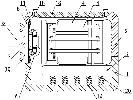
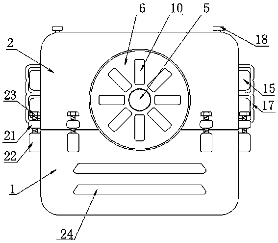
[0033] A permanent magnet motor for new energy vehicles, comprising a lower box 1 and an upper box 2, the surfaces of the upper box 2 and the lower box 1 are fixedly connected with sealing gaskets, the upper box 2 and the lower box 1 are both Made of plastic material, the motor body 4 has a good heat dissipation effect and a good shock absorption effect when in use, and can keep the output shaft 5 lubricated for a long time, which increases the versatility and practicability of the motor. The surface is provided with an air intake groove 24, which is inclined downward, and the inner cavity of the air intake groove 24 is fixedly connected with a filter screen, and there are multiple air intake grooves 24, which are evenly distributed on the surface of the lower box body 1 , the surface of the upper box 2 is fixedly connected with a first fixed block 21, and the surface of the lower box 1 is fixedly connected with a second fixed block 22, and the top of the first fixed block 21 i...

Embodiment 2

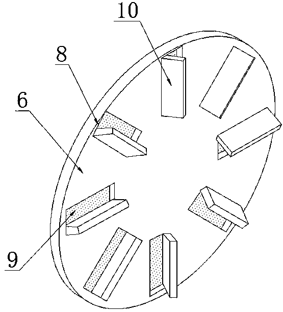
[0035] When working, the motor body 4 drives the output shaft 5 to rotate, and the output shaft 5 rotates in the limit bearing 7. When the output shaft 5 rotates, it drives the disc 6 to rotate, and the disc 6 drives the suction groove 8 and the drainage plate 10 to rotate, forming The eddy current draws the outside air along the air suction groove 8 into the lower box 1 and the upper box 2 along the annular groove 11 after being filtered by the first filter screen 9, and the upper box 2 and the lower box The hot air in 1 is discharged along the air intake groove 24 for air exchange. When the output shaft 5 rotates, the lubricating oil stored in the oil tank 13 in the oil storage tank 12 penetrates into the limit bearing 7 along the pipeline, and the limit bearing 7 Lubricate, the motor body 4 vibrates when it works, and drives the receiving plate 3 to move up and down, the receiving rod 19 slides up and down in the inner cavity of the receiving plate 3, the receiving plate 3 s...


PUM


Abstract

The invention discloses a permanent magnet motor for a new energy automobile. The permanent magnet motor comprises a lower box body and an upper box body, wherein the bottom of the upper box body is movably connected with the top of the lower box body, the inner cavity of the lower box body is fixedly connected with a bearing plate, the surface of the bearing plate is fixedly connected with a motor body, and the inner cavity of the motor body is rotatably connected with an output shaft. The invention relates to the technical field of permanent magnet motors. According to the invention, duringwork, the output shaft rotates and drives the disc to rotate at the same time, the disc drives the air suction groove and the flow guiding plate to rotate so as to form vortex flow, external air is pumped into the air suction groove along the air suction groove and is filtered by the first filter screen, the filtered air is introduced into the lower box body and the upper box body along the annular groove, the hot air in the upper box body and the lower box body is exhausted along the air inlet groove, and air exchange is performed, so that air exchange treatment can be performed while working, the balance between the temperature in the box bodies and the outside can be kept, the motor body is prevented from working at high temperature for a long time, and the motor body does not need to be driven by an additional power source.

Description

technical field [0001] The invention relates to the technical field of permanent magnet motors, in particular to a permanent magnet motor for new energy vehicles. Background technique [0002] Permanent magnet DC motors can be divided into permanent magnet brushless DC motors and permanent magnet brushed DC motors according to the presence or absence of brushes. Permanent magnet DC motors are a kind of DC motors that use permanent magnets to establish a magnetic field. Permanent magnet DC motors are widely used in various A portable electronic device or appliance, such as tape recorder, VCD player, record player, electric massager and various toys, is also widely used in automobiles, motorcycles, hand dryers, electric bicycles, battery cars, ships, aviation, machinery, etc. It is also widely used in some high-end products, such as video recorders, copiers, cameras, mobile phones, precision machine tools, bank money counting machines, money binding machines, etc. The stator w...

Claims


Application Information

Patent Timeline
Patent Type & Authority Applications(China)
IPC IPC(8): H02K9/06H02K9/26H02K5/24H02K9/19H02K5/20H02K5/04
CPCH02K9/06H02K9/26H02K5/24H02K9/19H02K5/20H02K5/04
Inventor 童彩琪
Owner 重庆市小电天体新能源汽车有限公司
Why Eureka
Try Eureka