
Gas appliance double-coil electromagnetic valve and thermocouple connecting structure with good anti-disengagement property

A connection structure, thermocouple technology, applied in the direction of connection, use of electromagnetic means, two-part connection device, etc., can solve the problems affecting the normal use of gas appliances, the connection part of the thermocouple, the connection part of the solenoid valve, and the failure to form a current loop. Achieve the effect of saving installation screw process, ensuring reliability and reducing installation cost

Pending Publication Date: 2020-08-11
奥可利电子(昆山)有限公司
View PDF0 Cites 3 Cited by
  • Summary
  • Abstract
  • Description
  • Claims
  • Application Information

AI Technical Summary

Problems solved by technology

However, in the actual installation process of the gas appliance, there are the following problems: when the external force is applied, the connection part of the thermocouple is very easy to fall out of the connection part of the solenoid valve
In this way, it will inevitably lead to the failure of the electrical connection between the pin assembly and the temperature-sensing head element and the electrical conduction between the ground wire terminal and the connection part of the solenoid valve, so that a current loop cannot be formed, which will affect the normal use of the gas appliance.

Method used


Image

  • Gas appliance double-coil electromagnetic valve and thermocouple connecting structure with good anti-disengagement property
  • Gas appliance double-coil electromagnetic valve and thermocouple connecting structure with good anti-disengagement property
  • Gas appliance double-coil electromagnetic valve and thermocouple connecting structure with good anti-disengagement property

Examples


Embodiment Construction

[0036] In the description of the present invention, it should be understood that the orientation or positional relationship indicated by the terms "upper", "lower", etc. is based on the orientation or positional relationship shown in the drawings, and is only for the convenience of describing the present invention and simplifying the description. It is not intended to indicate or imply that the referred device or element must have a particular orientation, be constructed in a particular orientation, and operate in a particular orientation, and thus should not be construed as limiting the invention.

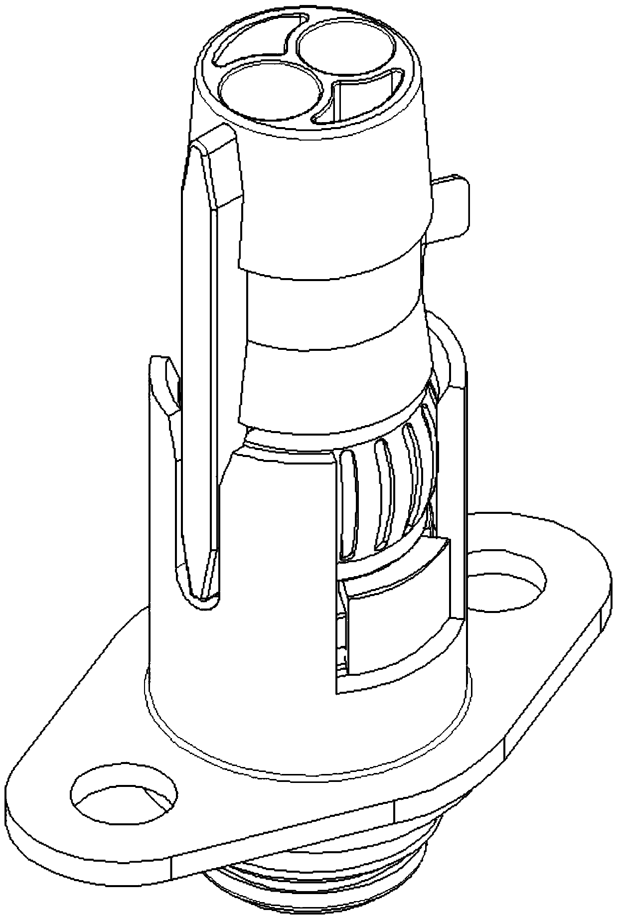
[0037] figure 2 It shows the structural schematic diagram of the double-coil electromagnetic valve and the thermocouple connection structure of the gas appliance with good detachment performance in the present invention. The wire terminal 4 is composed of several parts, wherein the solenoid valve connecting part 1 is arranged directly under the thermocouple connecting part 2 and ...


PUM


Abstract

The invention relates to a gas appliance double-coil electromagnetic valve and thermocouple connecting structure with a good anti-disengagement property. The connecting structure comprises an electromagnetic valve connecting part, a thermocouple connecting part, a thermocouple assembly and a ground wire terminal. The electromagnetic valve connecting part comprises a connecting support, a pin assembly and a base. The thermocouple connecting part comprises a connecting plastic cap and a core wire terminal assembly. The ground wire terminal is composed of a conductive sleeve and a wire pressing elastic piece. A temperature sensing head element and a temperature sensing shell of the thermocouple assembly are electrically connected with the pin assembly and the wire pressing elastic piece correspondingly. The conductive sleeve sleeves the connecting support. Clamping arms are arranged on the connecting plastic cap, and accordingly, an annular limiting groove is formed in the base. On one hand, the good grounding property of the thermocouple assembly is ensured on the premise of omitting the process of installing screws on a ground wire; on the other hand, the problem that wires of a plurality of thermocouples are twisted together during batched assembling is solved; and furthermore, it can be avoided that the electromagnetic valve connecting part is disengaged from the thermocoupleconnecting part.

Description

technical field [0001] The invention relates to the technical field of gas appliance manufacturing, in particular to a gas appliance double-coil electromagnetic valve and thermocouple connection structure with good detachment performance. Background technique [0002] The gas solenoid valve is a safety emergency cut-off device for gas pipelines. It can be connected with the gas leakage alarm system or with fire protection and other intelligent alarm control terminal modules to realize on-site or remote automatic / manual emergency cut-off of the gas source to ensure gas safety. When an accidental flameout or harmful strong vibration occurs, the solenoid valve will automatically close. The gas flameout protection devices on the market are mainly composed of thermocouple connection parts, solenoid valve connection parts and thermocouple components. The connecting part of the solenoid valve includes a connecting bracket and a pin assembly. The thermocouple assembly can generate...

Claims


Application Information

Patent Timeline
Patent Type & Authority Applications(China)
IPC IPC(8): F16K31/06F16K37/00G01K7/02G01K1/08G01K1/14H01R24/00H01R13/627H01R13/02H01R13/648
CPCF16K31/0679F16K37/0025G01K7/02G01K1/08G01K1/14H01R24/005H01R13/6271H01R13/02H01R13/648
Inventor 徐继业张宗国何祥铭何林
Owner 奥可利电子(昆山)有限公司
Learn More