Handheld garden wall ice clearing device
A wall and garden technology, which is applied in the field of hand-held wall deicing devices in gardens, can solve the problems of broken ice splashing, inconvenient planting vegetation, muddy soil, etc., and achieve the effect of reducing volume and gravity and saving cost
- Summary
- Abstract
- Description
- Claims
- Application Information
AI Technical Summary
Problems solved by technology
Method used
Image
Examples
specific Embodiment approach 1
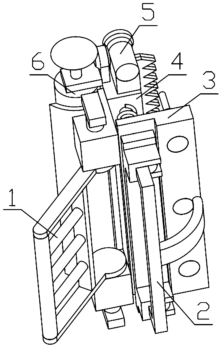
[0043] Combine below Figure 1-18 Describe this embodiment, a hand-held wall deicing device for gardens, including a handle mechanism 1, an auxiliary handle mechanism 2, an ice breaking mechanism 3, a toothed connection assembly 4, an ice sawing mechanism 5, and a cleaning mechanism 6. The ice sawing mechanism 5 is installed on the toothed connection assembly 4, the cleaning mechanism 6 is installed on the toothed connection assembly 4, the auxiliary handle mechanism 2 is fixedly installed on the toothed connection assembly 4, the ice breaking mechanism 3 is movably installed on the auxiliary handle mechanism 2, the handle mechanism 1 is fixedly installed on the toothed connection assembly 4, and the ice sawing mechanism 5 is engaged with the cleaning mechanism 6.
specific Embodiment approach 2
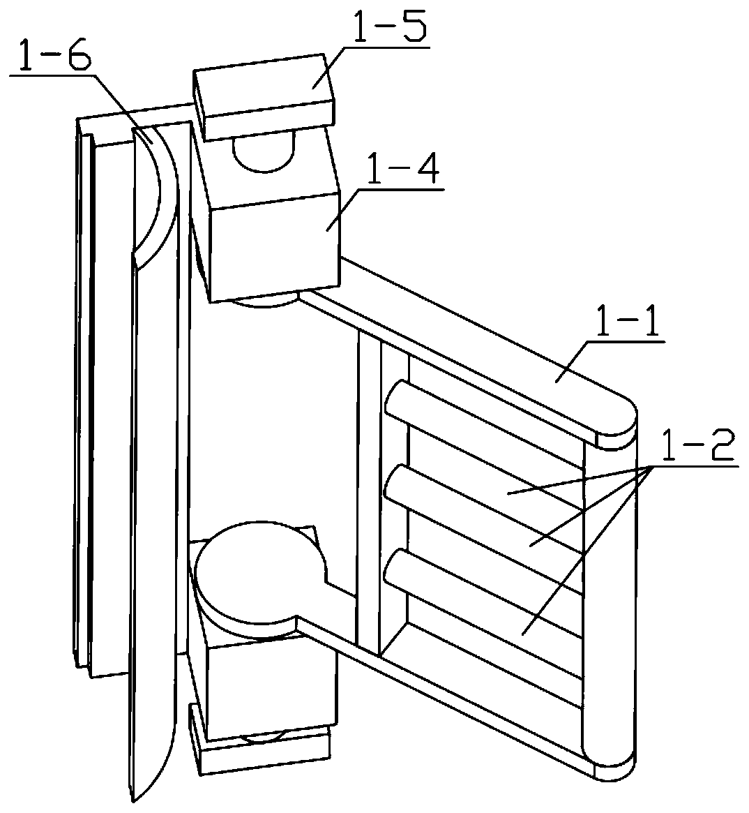
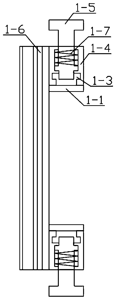
[0045] Combine below Figure 1-18Describe this embodiment, this embodiment will further explain Embodiment 1, the handle mechanism 1 includes a handle frame 1-1, a handle beam 1-2, a polygonal groove 1-3, a U-shaped frame 1-4, and a positioning insert 1-5, arc-shaped baffle 1-6, internal spring 1-7, the handle beam 1-2 is fixedly installed on the handle frame 1-1, there are two polygonal grooves 1-3, polygonal groove 1 -3 is fixedly installed on both sides of the handle frame 1-1, the polygonal groove 1-3 is rotatably installed on the groove provided on the U-shaped frame 1-4, and the positioning insert 1-5 is slidably installed on the U-shaped frame 1-4 On the groove provided above, the positioning insert 1-5 is movably installed in the groove provided on the polygonal groove 1-3, the internal spring 1-7 is set on the positioning insert 1-5, and the internal spring 1-7 is movably installed on the In the groove provided on the U-shaped frame 1-4, the arc-shaped baffle 1-6 is ...
specific Embodiment approach 3
[0047] Combine below Figure 1-18 Describe this embodiment, this embodiment will further explain the first embodiment, the auxiliary handle mechanism 2 includes a U-shaped handle 2-1, an arc-shaped pressing rod 2-2, a rotation limiter 2-3, a connecting cylinder 2- 4. Connect the support plate 2-5, the arc-shaped pressing rod 2-2 is fixedly installed on the U-shaped handle 2-1, there are two rotation limiters 2-3, and the rotation limiter 2-3 is fixedly installed On the U-shaped handle 2-1, the rotation limiter 2-3 is rotatably installed on the groove provided on the connection pallet 2-5, and the connection cylinder 2-4 is fixedly installed on the connection pallet 2-5, through the auxiliary The handle mechanism 2 can freely control the ice breaking mechanism 3, so that the ice breaking mechanism 3 can be operated to break thick ice when needed.
PUM
 Abstract
Description
Claims
Application Information
 - R&D
- Intellectual Property
- Life Sciences
- Materials
- Tech Scout
- Unparalleled Data Quality
- Higher Quality Content
- 60% Fewer Hallucinations
Browse by: Latest US Patents, China's latest patents, Technical Efficacy Thesaurus, Application Domain, Technology Topic, Popular Technical Reports.
© 2025 PatSnap. All rights reserved.Legal|Privacy policy|Modern Slavery Act Transparency Statement|Sitemap|About US| Contact US: help@patsnap.com


