Panel hanging device and its clamping arm
A technology of hanging device and clamping arm, which is applied in the field of panel hanging device and its clamping arm, which can solve problems such as panel damage, panel deformation, and inability to hang panels stably, so as to avoid shaking angle oversized effect
- Summary
- Abstract
- Description
- Claims
- Application Information
AI Technical Summary
Problems solved by technology
Method used
Image

Examples
Embodiment 1
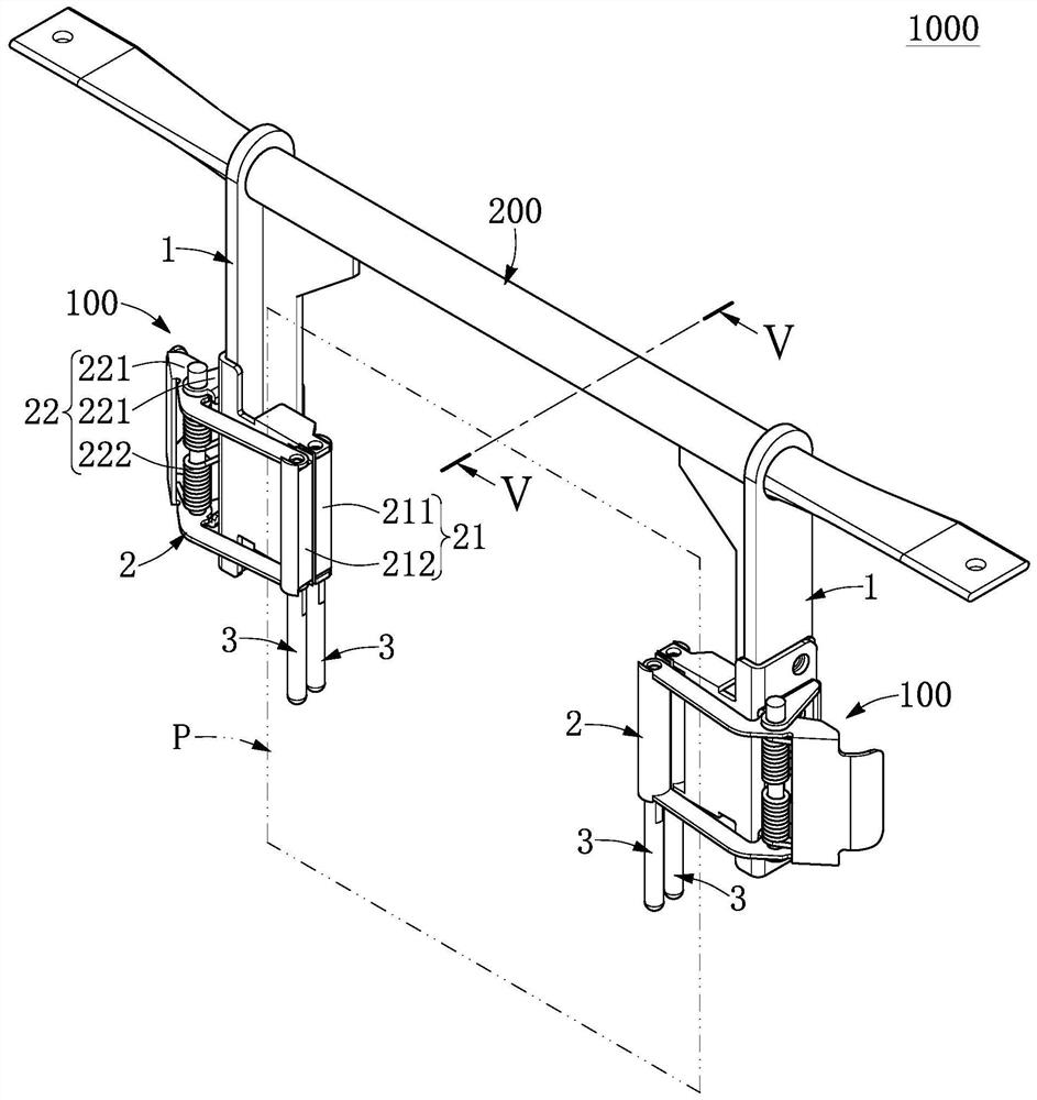
[0033] See Figures 1 to 7 Shown, embodiments of the present invention which is a. like Figure 1 to 3 , The present embodiment discloses a panel hanging device 1000, which can be used to detachably suspended a plate member B, B to facilitate transporting the plate member or plate B related facilitate processing procedures. Another point of view, the holding plate member fails to be in any form of suspension means is plate-shaped hanging device 1000 is not within the meaning of the present embodiment. Wherein said plate member B of the present embodiment is a circuit board will be described, but the present invention is not limited thereto.
[0034] like figure 1 with Figure 4 Shown, said plate member suspension device 1000 includes a crossbar 200 and suspended from the crossbar intervals two clamping arms 100,200 to one another. Wherein said rail structure 200 is elongate and which has a center axis C defines the axial direction, both ends of the cross bar 200 may be fixed to an ex...
Embodiment 2
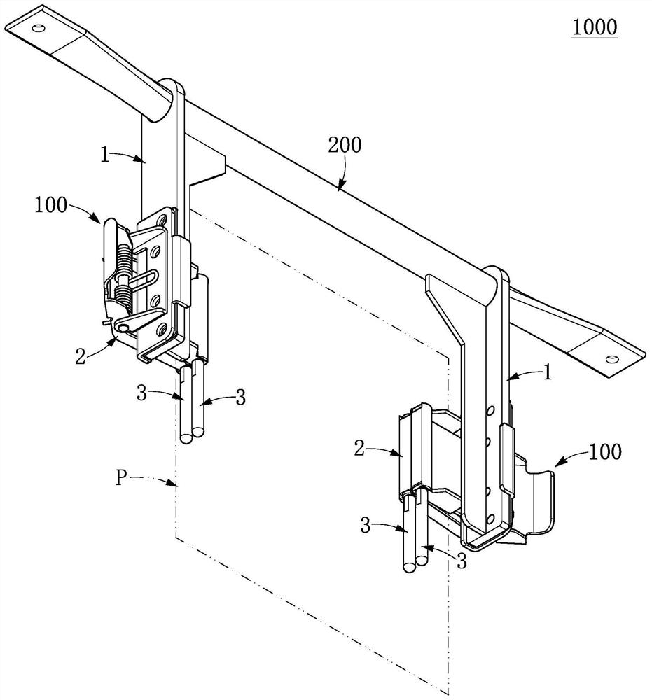
[0050] like Figures 8 to 11 As shown, it is the second embodiment of the present invention, and the present embodiment is similar to the above-described embodiment, so the same is no longer described in two embodiments, and the difference between the embodiment relative to the first example is, as follows:
[0051] In each of the clamping arms 100 of the present embodiment, the two limit members 3 are respectively formed to the fixed end 211 of the holding portion 21 and the movable end 212, and the active end 212 can be separated from The fixed end 211, and the two limit members 3 have a gap. Further, any of the limit members 3 is formed by the fixed end 211 (or movable end 212) extending in one direction of the axial direction, and the fixed end 211 and the corresponding limit piece thereof 3 The inner edge is substantially planar, and the inner edge of the active end 212 and the corresponding limit piece 3 thereof forms a height difference. In this embodiment, the movable end 2...
Embodiment 3
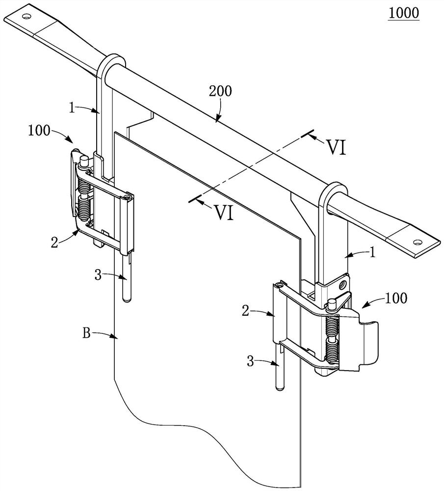
[0054] like Figure 12 to 14 As shown, it is the third embodiment of the present invention, and the present embodiment is similar to the above-described embodiment, so the same is no longer described in the same amount of the two embodiments, and the difference between the embodiment relative to the first example is, as follows:
[0055] In each of the clamping arms 100 of the present embodiment, the two limit members 3 are coupled to the carrier portion 12 of the arm body 1, and each limit piece 3 and the carrier portion 12 can be integrated. The invention is not limited herein. Furthermore, in each of the clamping arm 100 of the present embodiment, the jig 2 is a substantially central portion fixed to the carrier portion 12, and the two limit members 3 are the bottom block connected to the carrier portion 12, and The two limit pieces 3 are substantially located at the fixed end 211 of the clamping portion 21 and the positive part of the movable end 212.
[0056] Further, accordin...
PUM
 Abstract
Description
Claims
Application Information
 - R&D
- Intellectual Property
- Life Sciences
- Materials
- Tech Scout
- Unparalleled Data Quality
- Higher Quality Content
- 60% Fewer Hallucinations
Browse by: Latest US Patents, China's latest patents, Technical Efficacy Thesaurus, Application Domain, Technology Topic, Popular Technical Reports.
© 2025 PatSnap. All rights reserved.Legal|Privacy policy|Modern Slavery Act Transparency Statement|Sitemap|About US| Contact US: help@patsnap.com