
Garbage compression equipment capable of improving compression efficiency

A technology of garbage compression and compression efficiency, which is applied in the direction of garbage transmission, garbage collection, presses, etc., which can solve the problems of increasing the number of pressing down of the pressing plate, affecting the normal life of nearby residents, and increasing the energy consumption of the hydraulic tank, so as to reduce time and eliminate waste. Odor, the effect of improving compression efficiency

Active Publication Date: 2020-08-11
武汉市绿色环保能源有限公司
View PDF6 Cites 2 Cited by
  • Summary
  • Abstract
  • Description
  • Claims
  • Application Information

AI Technical Summary

Problems solved by technology

[0003] During the use of the existing vertical garbage bins, after pouring the garbage into the garbage bin, the garbage is squeezed by moving the pressure plate down, thereby reducing the volume of the garbage. During this process, the distribution of garbage is different, and only the pressure plate Under the premise of achieving capacity reduction efficiency, it is necessary to increase the number of pressing down of the pressure plate. In this case, it is easy to increase the energy consumption of the hydraulic tank, and in hot summer, the waste compression set up near the community During the garbage disposal process, it is easy to emit foul smell, which affects the normal life of nearby residents. At the same time, the staff are also easily affected by the bad smell when transporting compressed garbage.

Method used


Image

  • Garbage compression equipment capable of improving compression efficiency
  • Garbage compression equipment capable of improving compression efficiency
  • Garbage compression equipment capable of improving compression efficiency

Examples


Embodiment 1

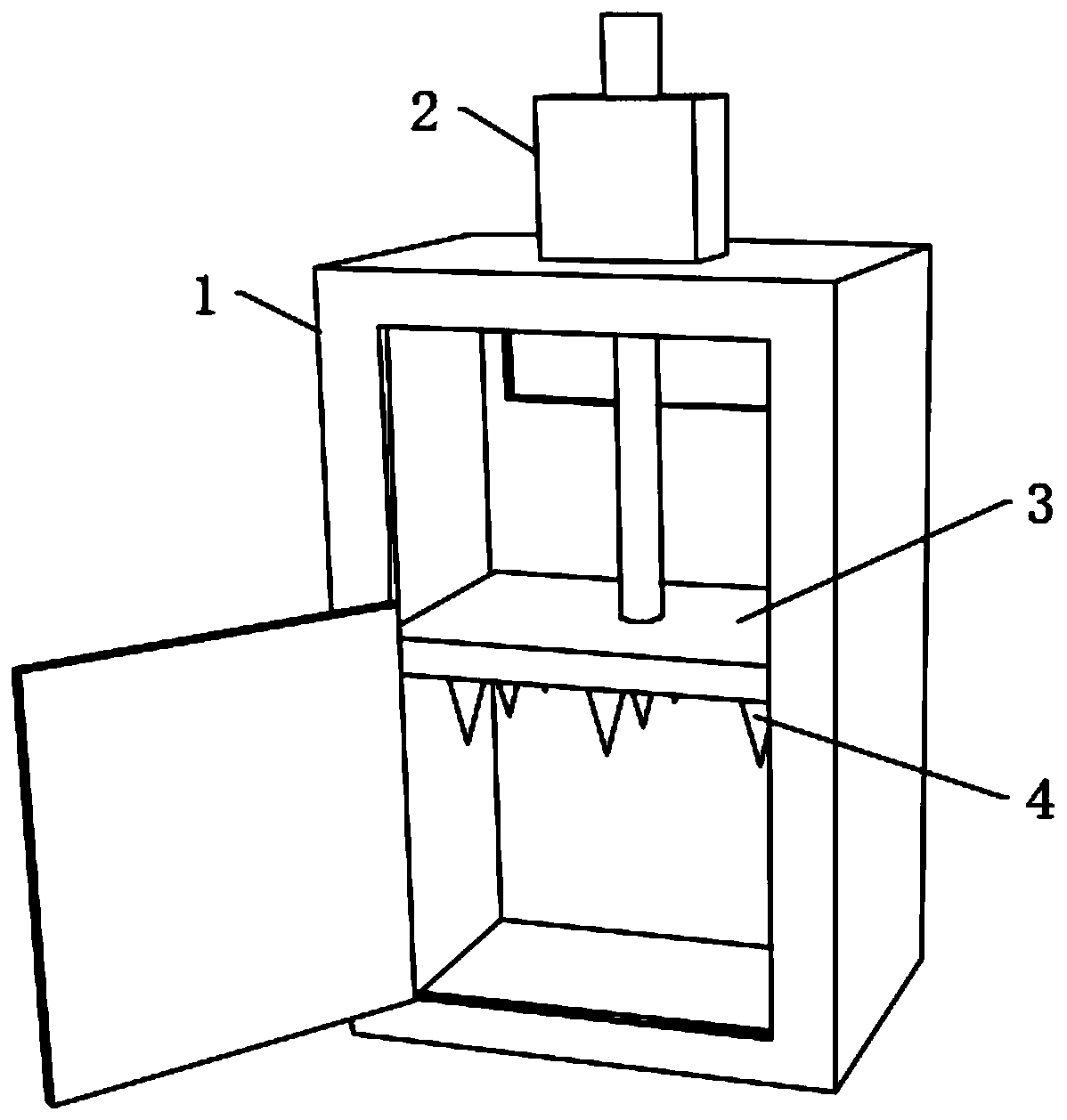
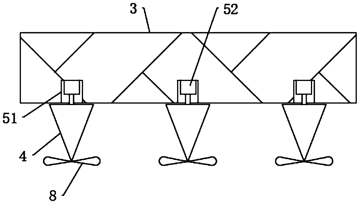
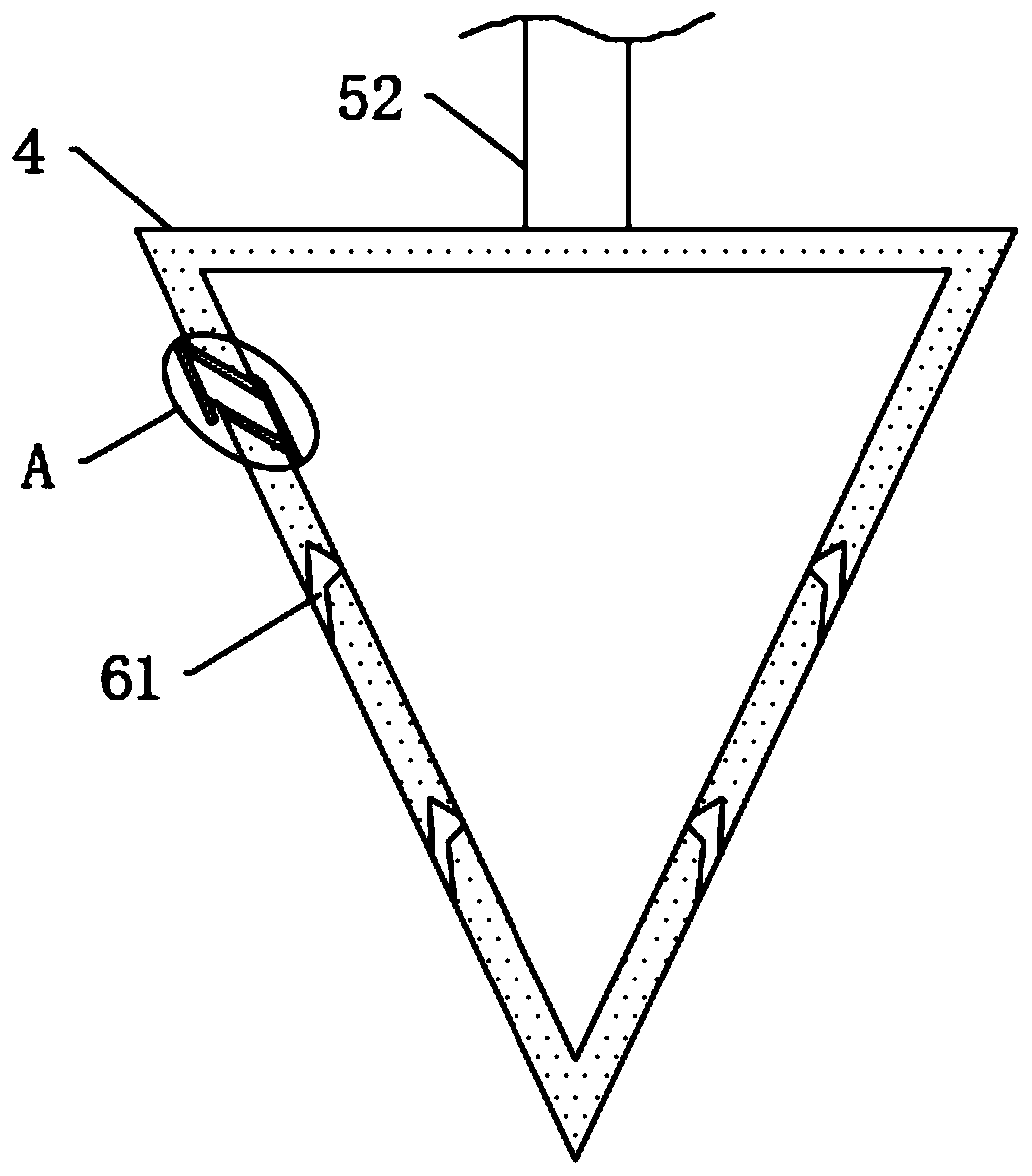
[0042] see figure 1 , a garbage compression device that can improve compression efficiency, including a garbage compression box body 1 with a switch door, a controller is installed on the outer end of the garbage compression box body 1, and a hydraulic tank 2 and a micro-motor 52 are electrically connected to the controller , the upper end of the garbage compression box body 1 is equipped with a hydraulic tank 2, the output end of the hydraulic box 2 runs through the inner top of the garbage compression box body 1 and is fixedly connected with a pressure plate 3, the pressure plate 3 is slidingly connected with the inner wall of the garbage compression box body 1, and the pressure plate 3 is lowered There are multiple sets of evenly distributed hollow conical columns 4 on the side.

[0043] see figure 2 , the bottom end of the pressing plate 3 is dug with a plurality of groups of installation grooves 51 corresponding to the hollow conical column 4, and the top end of the ins...


PUM


Abstract

The invention discloses garbage compression equipment capable of improving compression efficiency, and belongs to the field of garbage disposal. The garbage compression equipment capable of improvingcompression efficiency comprises a garbage compression box body having an opening-closing door; a hydraulic box is installed at the upper end of the garbage compression box body, and the output end ofthe hydraulic box penetrates through the inner top end of the garbage compression box body and is fixedly connected with a compression plate; the compression plate is slidably connected with the inner wall of the garbage compression box body, and the lower side of the compression plate is provided with a plurality of sets of uniformly-distributed hollow conical columns; by arranging the hollow conical columns and rotary blades, the position and volume of part of garbage in a garbage pile can be changed, accordingly, the compression efficiency of compression plate to the garbage is improved, the compression time is shortened, and energy consumption generated in the working process of the hydraulic box is reduced; and by arranging a deodorant, the hollow conical columns scatter the deodorant into the garbage in the moving process, unpleasant odor of the garbage can be effectively removed, and thus, staff are not prone to being influenced by the unpleasant odor in the process of transporting the compressed garbage.

Description

technical field [0001] The invention relates to the field of garbage disposal, in particular to a garbage compression device capable of improving compression efficiency. Background technique [0002] Household garbage is often collected by garbage collection vehicles and then transported to the garbage transfer station, where the garbage compressor is used to press the garbage into the garbage compression box, and then transported by the garbage truck to the garbage disposal site for centralized treatment. Garbage compression equipment is one of the main equipment to achieve garbage compression and volume reduction, and it is also the main processing equipment of the garbage transfer station. The garbage compressor is the main equipment of the garbage transfer station. It is controlled by the hydraulic system to compress the collected garbage, which can reduce the volume of garbage, so as to reduce the empty load rate of garbage trucks and reduce transportation costs. To re...

Claims


Application Information

Patent Timeline
Patent Type & Authority Applications(China)
IPC IPC(8): B30B9/00B30B15/00B30B15/08B09B3/00B65F9/00
CPCB30B9/00B30B15/0052B30B15/08B09B3/00B65F9/00
Inventor 郭学章
Owner 武汉市绿色环保能源有限公司
Learn More