
Pipetting device capable of self-checking air tightness and accurately extracting and pipetting method thereof

A pipetting device and air-tightness technology, which is applied in the direction of fluid tightness testing, measuring devices, chemical instruments and methods, etc., and can solve problems such as poor sealing, inability to accurately detect, and inability to accurately measure the volume of extracted sample fluid, etc. problem, to achieve the effect of simple structure and small volume

Inactive Publication Date: 2020-08-11
TB HEALTHCARE BIOTECHNOLOGY (GUANGDONG) CO LTD
View PDF6 Cites 2 Cited by
  • Summary
  • Abstract
  • Description
  • Claims
  • Application Information

AI Technical Summary

Problems solved by technology

[0002] The airtightness of the existing medical equipment pipetting system relies on the installation process and real-time and regular inspections by human eyes to ensure its airtightness. Biocontaminated samples will cause certain pollution consequences; in addition, when the samples need to be processed in proportion, the existing pipetting system cannot accurately measure the liquid volume of the extracted samples

Method used


Image

  • Pipetting device capable of self-checking air tightness and accurately extracting and pipetting method thereof

Examples


Embodiment 1

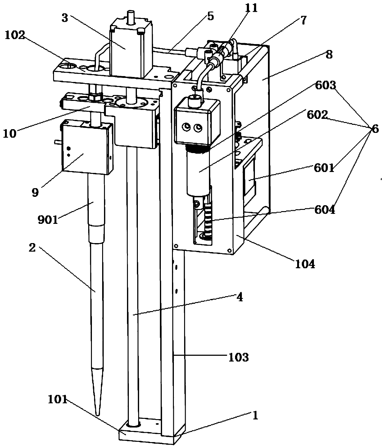
[0026] Such as figure 1 As shown, this embodiment provides a pipetting device that can self-check airtightness and accurately extract, including the following components:

[0027] Frame 1, described frame 1 comprises base 101, upper support plate 102, side support plate 103 and side support 104, and the two ends of described side support plate 103 are connected with described base 101 and described upper support plate 102 respectively , the side bracket 104 is arranged on the side support plate 103;

[0028] A suction mechanism, arranged on the side support 104, is used to suck the sample in the sample container;

[0029] The lifting mechanism is arranged on the upper support plate 102, which includes a second slider 10, which can rise or fall along the height direction of the side support plate 103;

[0030] The pipetting mechanism is arranged on the second slider 10 and is used to pipette the sample in the sample container.

[0031] In this embodiment, preferably, the suc...

Embodiment 2

[0039] Such as figure 1 As shown, this embodiment provides a method of operating a pipetting device that can self-test airtightness and accurately extract, including the following steps:

[0040] (1) When drawing a sample, first start the lifting motor 3, and the liquid pipetting mechanism moves down to the designated position above the sample tube under the drive of the lifting motor 3, and then starts the liquid pipetting motor 601. The piston 603 moves downward to generate a suction force, and the gun head 2 sucks the sample under the action of the suction force. During the process of sucking the sample and after the sample is taken, by monitoring the pressure change of the pressure sensor 7, it is known that The amount of the sample drawn, and the numerical value of the sample amount drawn will be displayed by the controller 8;

[0041] (2) When discharging the sample, the piston 603 moves upward to generate a thrust, and the pipetting mechanism discharges the sample in t...


PUM


Abstract

The invention relates to a pipetting device capable of self-checking air tightness and accurately extracting, which comprises the following components: a rack, the rack comprises a base, an upper support plate, a side support plate and a side bracket, two ends of the side support plate are respectively connected with the base and the upper support plate, and the side bracket is arranged on the side support plate; a suction mechanism is arranged on the side bracket and is used for sucking a sample; a lifting mechanism is arranged on the upper supporting plate, comprises a second sliding block and can ascend or descend in the height direction of the side supporting plates; and a pipetting mechanism is arranged on the second sliding block and is used for pipetting the sample. The device is simple in structure, small in size and capable of meeting the requirements of the field of biomedical instruments for small and precise pipetting devices.

Description

technical field [0001] The invention relates to a pipetting device and method capable of self-testing air tightness and accurate extraction, belonging to the technical field of biomedical devices. Background technique [0002] The airtightness of the existing medical equipment pipetting system relies on the installation process and real-time and regular inspections by human eyes to ensure its airtightness. Biocontaminated samples will cause certain pollution consequences; in addition, when the samples need to be processed in proportion, the existing pipetting system cannot accurately measure the liquid volume of the extracted samples. Contents of the invention [0003] In view of the above outstanding problems, the present invention provides a liquid pipetting device and method that can self-check the air tightness and extract accurately. The device of the present invention can monitor the pressure in the process of pipetting in real time by adding a pressure sensor, there...

Claims


Application Information

Patent Timeline
Patent Type & Authority Applications(China)
IPC IPC(8): B01L3/02G01M3/32
CPCB01L3/0293G01M3/3272
Inventor 毕利军马文美杨晓马道稳
Owner TB HEALTHCARE BIOTECHNOLOGY (GUANGDONG) CO LTD
Learn More