
High-precision bone saw

A high-precision, bone saw technology, applied in surgical saw, medical science, surgery, etc., can solve the problems of cutting error, increase the labor intensity of medical personnel, and the influence of human factors, and achieve convenient use, simple structure, and avoid errors. Effect

Active Publication Date: 2020-08-11
郭庆丰
View PDF10 Cites 1 Cited by
  • Summary
  • Abstract
  • Description
  • Claims
  • Application Information

AI Technical Summary

Problems solved by technology

[0004] The purpose of the present invention is to solve the problem that most of the bones are cut by medical personnel holding bone saws, which is greatly affected by human factors, prone to cutting errors, and increases the cost of medical work. Due to the shortcomings of the labor intensity of personnel, a high-precision bone saw is proposed

Method used


Image

  • High-precision bone saw
  • High-precision bone saw
  • High-precision bone saw

Examples


Embodiment 1

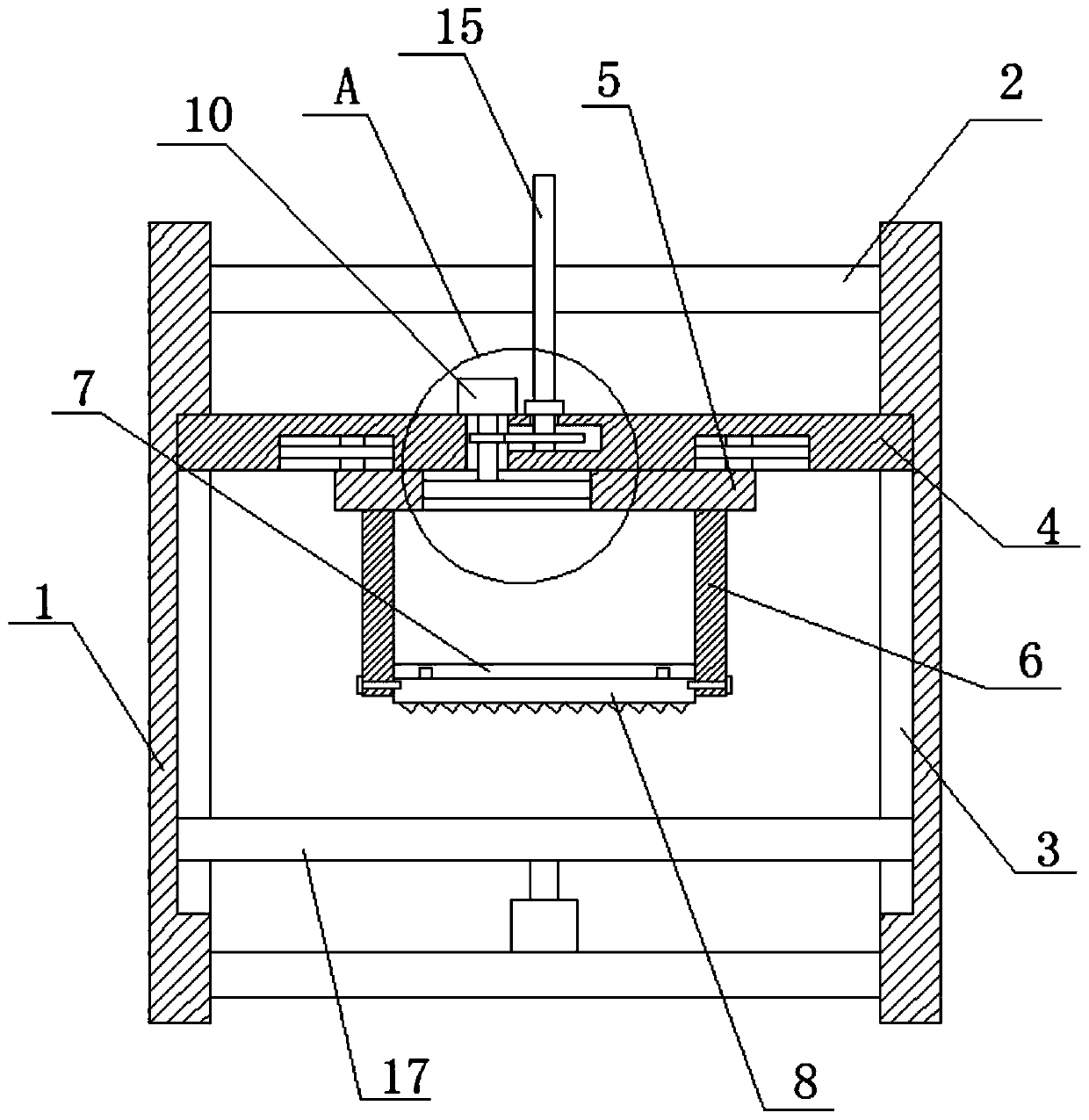
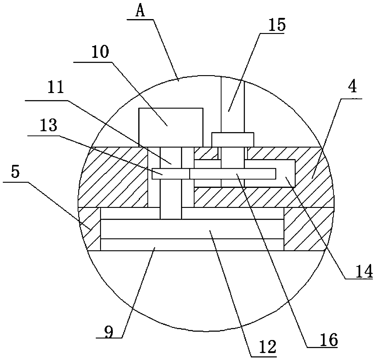
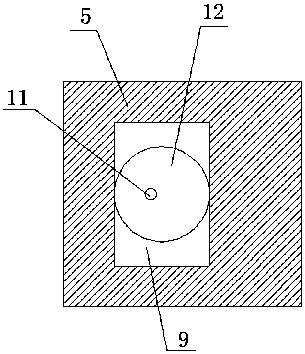
[0020] refer to Figure 1-3 , a high-precision bone saw, including two vertical boards 1, the sides of the two vertical boards 1 close to each other are provided with chute 3, and the two chute 3 are slidingly installed with a placement plate 17 and a pressure plate 4, the pressure plate 4 The bottom of the horizontal moving plate 5 is slidably installed with two vertical mounting plates 6 fixedly mounted on the bottom of the horizontal moving plate 5, and the side of the two vertical mounting plates 6 close to each other is fixedly mounted with the same bearing plate 7, the bearing plate The bottom of 7 is equipped with saw 8, offers vertical hole 9 on the horizontal moving plate 5, and the top of pressing plate 4 is fixedly installed with motor 10, and the output shaft of motor 10 is fixedly installed with an end of vertical bar 11, and the other end of vertical bar 11 An eccentric wheel 12 is fixedly installed, the outer side of the eccentric wheel 12 is in contact with the...

Embodiment 2

[0026] refer to Figure 1-3 , a high-precision bone saw, including two vertical boards 1, the sides of the two vertical boards 1 close to each other are provided with chute 3, and the two chute 3 are slidingly installed with a placement plate 17 and a pressure plate 4, the pressure plate 4 The bottom of the horizontal moving plate 5 is slidingly installed with a horizontal moving plate 5, and the bottom of the horizontal moving plate 5 is fixedly installed with two vertical mounting plates 6 by welding, and the side of the two vertical mounting plates 6 close to each other is fixedly installed with the same bearing plate by welding 7. A saw 8 is installed on the bottom of the bearing plate 7, a vertical hole 9 is provided on the horizontal moving plate 5, a motor 10 is fixedly installed on the top of the pressure plate 4 by welding, and a vertical rod 11 is fixedly installed on the output shaft of the motor 10 by welding. One end, the other end of the vertical rod 11 is fixedl...


PUM


Abstract

The invention belongs to the technical field of a bone saw, and particularly relates to a high-precision bone saw. In accordance with the problems that most of conventional bone saws are held by medical personnel for cutting bones, so that influence of human factors is large, cutting errors are easy to generate, and the labor intensity of the medical personnel is strengthened, the invention provides the high-precision bone saw. The high-precision bone saw is characterized by comprising two vertical plates, wherein sliding grooves are formed in one sides which are mutually closed to each other,of the two vertical plates; a placing plate and a pressing plate are mounted in the two sliding grooves in a sliding manner; a horizontal moving plate is mounted at the bottom of the pressing plate in the sliding manner; two vertical mounting plates are fixedly mounted at the bottom of the horizontal moving plate; the same bearing plate is fixedly mounted on one sides which are mutually close toeach other, of the two vertical mounting plates; and a saw is mounted at the bottom of the bearing plate. The high-precision bone saw disclosed by the invention can replace labor to perform amputation, so that the working intensity of medical personnel is reduced, errors caused by labor are avoided, and the high-precision bone saw is higher in accuracy, simple in structure and convenient to use.

Description

technical field [0001] The invention relates to the technical field of bone saws, in particular to a high-precision bone saw. Background technique [0002] The bone saw is an orthopedic surgical instrument. When amputation is performed, the bone saw is used to cut the bone. [0003] In the prior art, most of the bones are cut by the medical staff holding the bone saw, which is greatly affected by human factors, prone to cutting errors, and increases the labor intensity of the medical staff. Therefore, we propose a high-precision bone saw that uses to solve the above problems. Contents of the invention [0004] The purpose of this invention is to solve the disadvantages that most of the bones are cut by hand-held bone saws by medical personnel, which is greatly affected by human factors, prone to cutting errors, and increases the labor intensity of medical personnel. A high-precision bone saw is proposed. saw. [0005] In order to achieve the above object, the present in...

Claims


Application Information

Patent Timeline
Patent Type & Authority Applications(China)
IPC IPC(8): A61B17/14A61B17/16
CPCA61B17/142A61B17/1657A61B2017/564
Inventor 郭庆丰吴洋
Owner 郭庆丰
Learn More