
Use of an assist motor of a power steering system to generate test cycles according to a position ascertaining cycle

A power steering and auxiliary motor technology, which is applied in power steering mechanism, vehicle testing, machine/structural component testing, etc., can solve the problems of wrong steering direction, expensive, inaccurate, etc., and achieve the effect of accurate measurement

Pending Publication Date: 2020-08-07
JTEKT EURO
View PDF0 Cites 0 Cited by
  • Summary
  • Abstract
  • Description
  • Claims
  • Application Information

AI Technical Summary

Problems solved by technology

[0003] Of course, such manual manipulation is sometimes very tedious and is often relatively inaccurate, since the operator cannot apply accurate velocity or force setpoints, especially constant value setpoints, in a reliable and reproducible manner, which might otherwise (e.g. ) gets the steering direction wrong within a cycle, which can distort the estimate of the desired characteristic
[0004] Furthermore, if it is absolutely conceivable to replace the operator with a robotic arm manipulating the steering wheel, such a solution would be particularly complex and expensive to implement, especially since for each test the robotic arm would have to be mounted and connected to the steering System model for physical reconfiguration of robotic arm and test bench

Method used


Image

  • Use of an assist motor of a power steering system to generate test cycles according to a position ascertaining cycle
  • Use of an assist motor of a power steering system to generate test cycles according to a position ascertaining cycle
  • Use of an assist motor of a power steering system to generate test cycles according to a position ascertaining cycle

Examples


Embodiment Construction

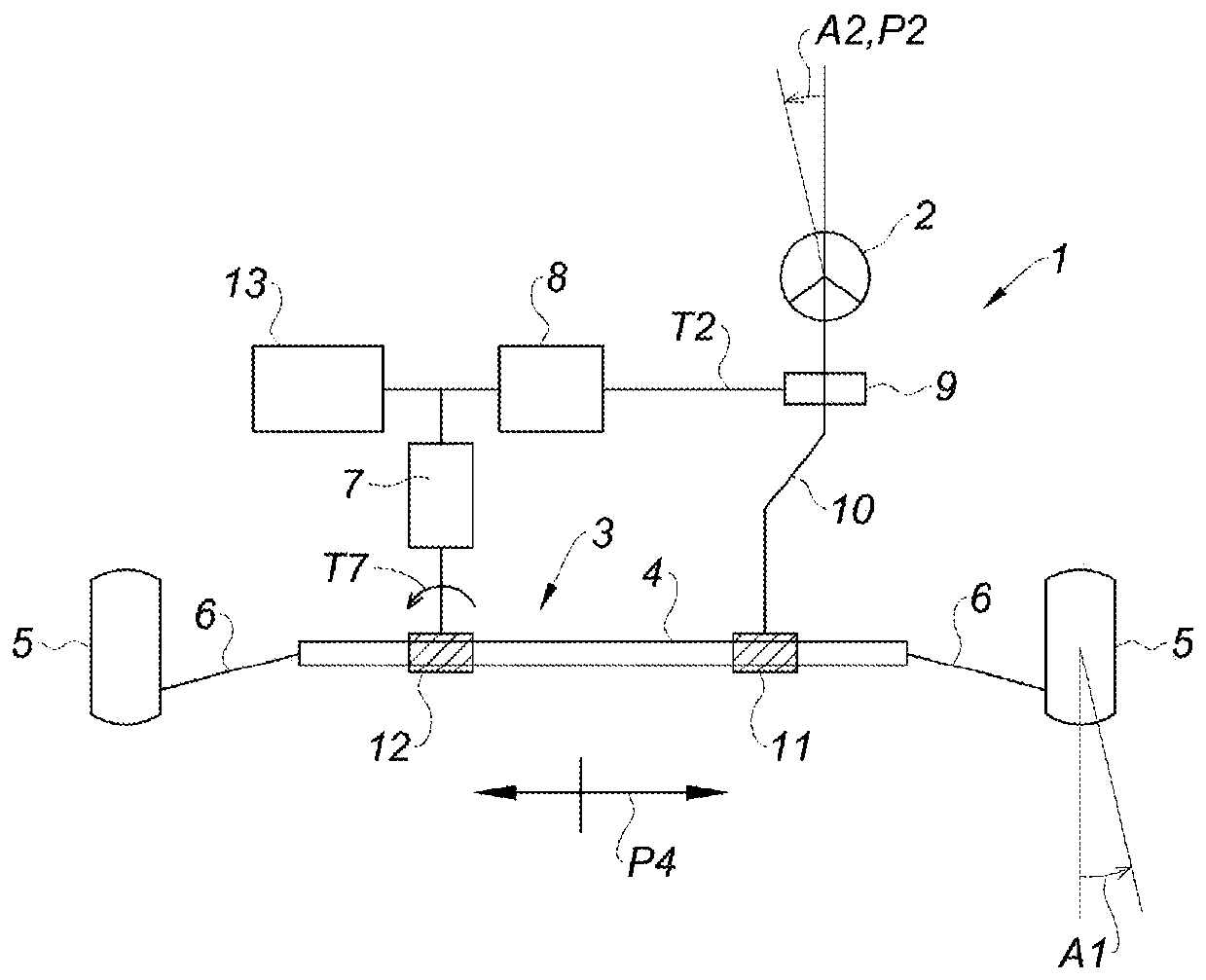
[0018] The invention relates to a method for characterizing a power steering system 1 , which aims at empirically determining at least one characteristic of said power steering system 1 , called “desired characteristic”, which is specific to said system.

[0019] Such as figure 1 As shown, said power steering system 1 comprises at least one heading definition device 2 which allows defining an orientation, referred to as the "steering angle" A1 of the power steering system.

[0020] Preferably, the heading defining means 2 will comprise a steering wheel 2 allowing a (human) driver to freely define said steering angle A1 to ensure manual control of a vehicle equipped with a power steering system 1 .

[0021] The steering system also comprises a steering mechanism 3 having at least one movable member 4, such as a rack 4, whose position P4 is adapted to correspond to the selected steering angle.

[0022] For the sake of convenience, the movable member 4 can be assimilated as a ra...


PUM


Abstract

The invention relates to a method for characterizing a power steering system (1) for empirically determining at least one property of said system (1), said power steering system comprising at least one steering wheel (2), a steering mechanism (3) provided with a rack (4), and at least one assist motor (7), said method comprising, outside a steering phase during which the power steering system (1)is assigned to the driving of a vehicle in order to cause said vehicle to follow a trajectory which is determined as a function of the situation of said vehicle with respect to its environment, a step(a) of automatically activating the assist motor (7), during which step a computer (13) is used to automatically generate and apply to the assistance motor (7), without requiring any external actionon the steering wheel (2), an activation instruction that follows one or more cycles referred to as pre-established exploration cycles (CY) for measuring, during the at least one exploration cycle orat the end of said at least one exploration cycle (CY), at least one indicator parameter (P7_mes, T7_mes, P4_mes, T2_mes, V2_mes) which is specific to the response by the power steering system to theautomatic activation of the assist motor and which is characteristic of the desired property.

Description

technical field [0001] The present invention relates to a characterization method aimed at empirically determining at least one characteristic of a power steering system, such as the position of the end-of-travel stop of the steering rack or the power steering, when developing or calibrating the power steering system in the factory The frequency response characteristics of the system. Background technique [0002] The known characterization method requires the operator to install the power steering system on the test bench, and then manipulate the steering wheel according to the preset special manipulation cycle, so that the sensors and recorders equipped with the test bench can observe the reaction of the steering system and measure the index parameters, The desired properties can thus be quantified. [0003] Of course, such manual manipulation is sometimes very tedious and is often relatively inaccurate, since the operator cannot apply accurate velocity or force setpoints...

Claims


Application Information

Patent Timeline
IPC IPC(8): G01M17/007
CPCG01M17/007B62D5/0463B62D5/0487B62D15/021
Inventor 马蒂厄·卢索克里斯多夫·拉维耶
Owner JTEKT EURO
Learn More