
Desiccant fitting

A technology of accessories and components, applied in the field of dehumidification accessories, can solve the problems of high transmission force and equipment cost, and achieve the effect of improving the adjustment effect

Active Publication Date: 2020-08-07
YAZAKI ENERGY SYST
View PDF5 Cites 0 Cited by
  • Summary
  • Abstract
  • Description
  • Claims
  • Application Information

AI Technical Summary

Problems solved by technology

Therefore, transmission force and equipment costs become prohibitive

Method used


Image

  • Desiccant fitting
  • Desiccant fitting
  • Desiccant fitting

Examples


Embodiment Construction

[0027] Hereinafter, the present invention will be described together with preferred embodiments. In addition, this invention is not limited to embodiment demonstrated below, It can change suitably in the range which does not deviate from the summary of this invention. In addition, in the embodiments described below, some components are not shown or described, but about omitted technical details, it is needless to say that within a range not inconsistent with the following, known or well known technology.

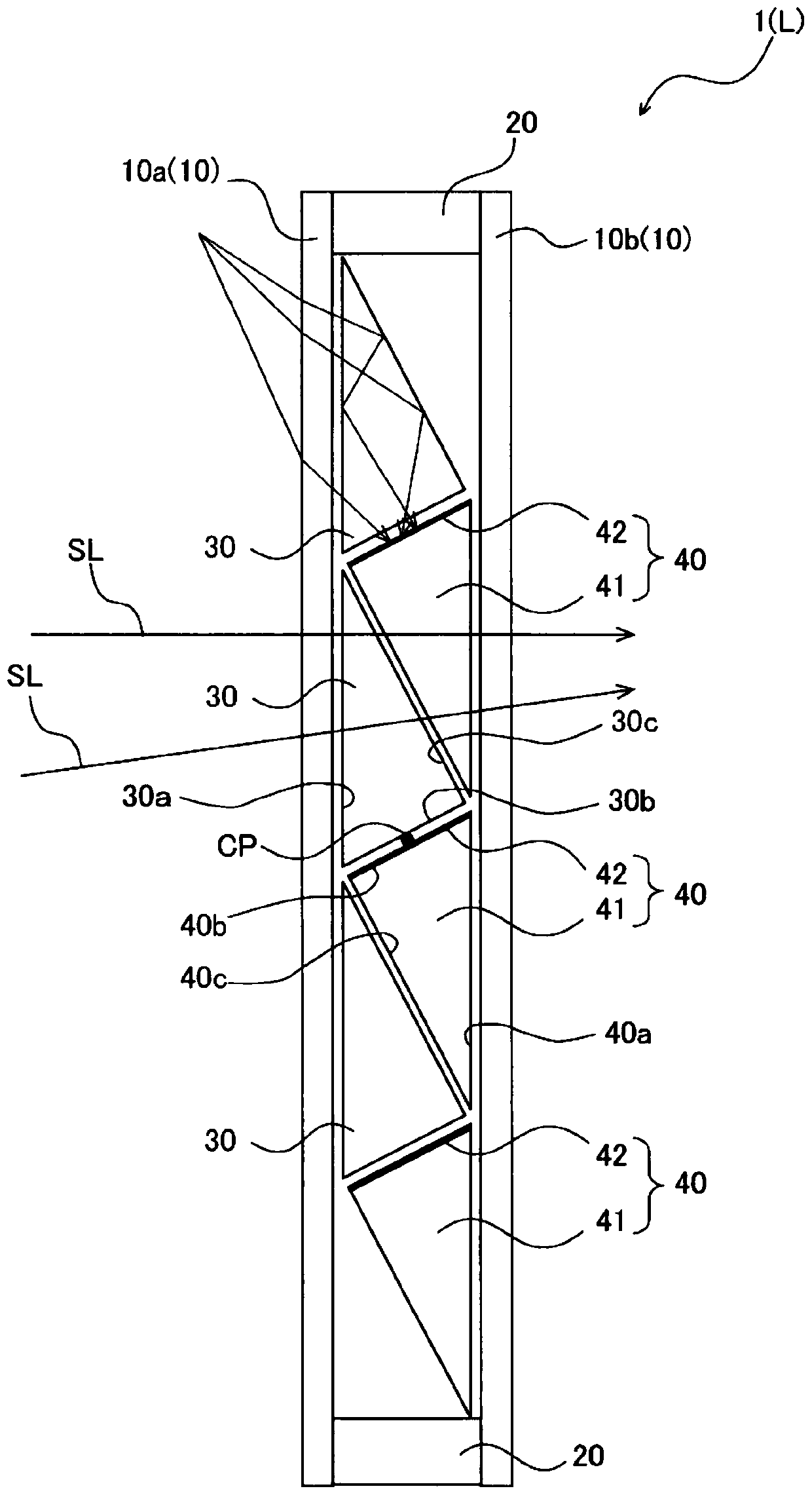
[0028] figure 1 It is a cross-sectional view showing the dehumidification window according to the first embodiment of the present invention. In the following, a desiccant window that can be used as a window (whether the window can be opened or closed) will be described as an example of a desiccant fitting, but the desiccant fitting is not limited to being applied to a window, and can be an outer wall material Wait.

[0029] figure 1 The desiccant window 1 of the illustr...


PUM


Abstract

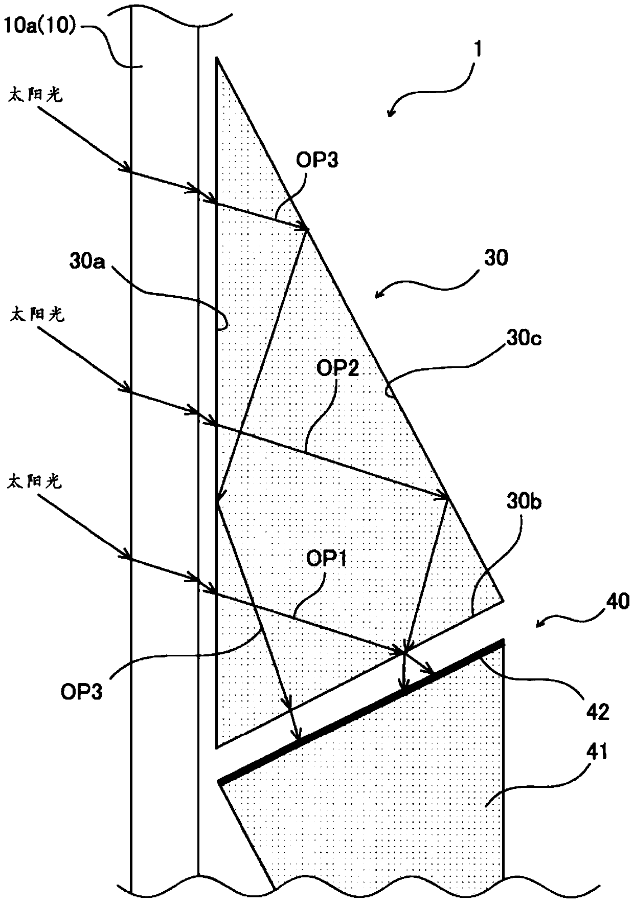
Provided is a desiccant fitting that is capable of enhancing an indoor humidity control effect. A desiccant window (1) is provided with: a transparent triangular prism (30) that is disposed between first and second plate materials (10a, 10b), that includes a first edge (30a) along the first glass (10a) in a cross-sectional view and second and third edges (30b, 30c) having angles with respect to the first edge (30a), and that forms three types of optical paths; and a desiccant heat reception part (40) that is moisture-absorptive, that is disposed between the first and second plate materials (10a, 10b), that is installed oppositely to the second edge (30b) of the triangular prism (30), and that receives solar heat so as to discharge the absorbed moisture by heating same with the received heat.

Description

technical field [0001] The invention relates to a dehumidifying accessory. Background technique [0002] In the prior art, a dehumidification system with a hygroscopic agent transports indoor air and the atmosphere through ducts, etc., and utilizes the hygroscopic agent to perform moisture absorption and regeneration in a mechanical device. Therefore, transmission force and equipment cost become excessively high. [0003] Therefore, a hygroscopic structure (dehumidifying accessory) that can be used as an accessory has been proposed (refer to Patent Document 1). The hygroscopic structure includes a wall with moisture absorption and deodorizing effects and glass that forms an air layer with the wall on the outdoor side of the wall. By making the air layer communicate with the indoor side, the room is dehumidified, and the air layer is connected to the room. The outside is connected, moisture is released and the wall is regenerated. [0004] reference list [0005] patent d...

Claims


Application Information

Patent Timeline
Patent Type & Authority Applications(China)
IPC IPC(8): E06B5/00B01D53/26B01D53/28E04B1/76
CPCB01D53/26B01D53/28E04B1/76E06B5/00E06B3/6715E06B3/6612E06B9/24E06B2009/2417E06B7/12Y02A30/249Y02B80/22B01D2257/80E04B1/70F24F3/1411
Inventor 中村拓树
Owner YAZAKI ENERGY SYST
Learn More