Full-bridge module and direct-current circuit breaker

A DC circuit breaker and branch circuit technology, which is applied to circuits, emergency protection circuit devices, electrical components, etc., can solve the problems of increasing cost and floor area, reducing device utilization, and large distribution parameters, so as to reduce equipment cost and The effect of volume, quantity reduction and utilization improvement

Pending Publication Date: 2020-08-07
GLOBAL ENERGY INTERCONNECTION RES INST CO LTD +2
View PDF2 Cites 2 Cited by
  • Summary
  • Abstract
  • Description
  • Claims
  • Application Information

AI Technical Summary

Problems solved by technology

[0004] Aiming at the large volume of equipment caused by the cascading of a large number of sub-modules, and the large distribution parameters lead to high overvoltage, which reduces the utilization rate of the device, increases the cost and occupies an area, the present invention provides a fully Bridge modules, specifically:

Method used


Image

  • Full-bridge module and direct-current circuit breaker
  • Full-bridge module and direct-current circuit breaker
  • Full-bridge module and direct-current circuit breaker

Examples


Embodiment 1

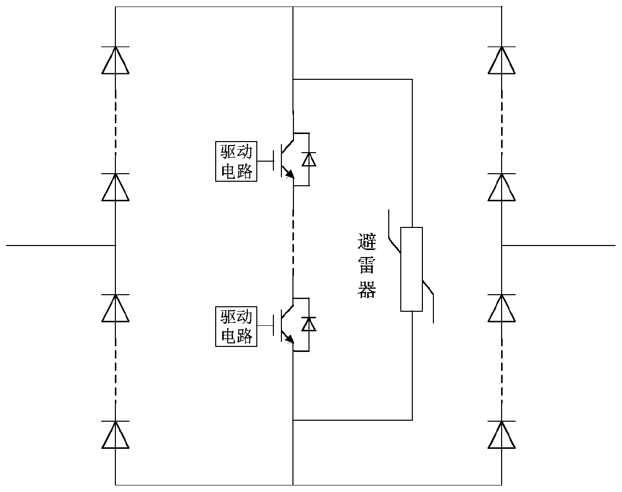
[0047] The invention provides a full-bridge module. The novel full-bridge module based on the series connection of semiconductor devices is composed of semiconductor devices (including fully-controlled power electronic devices, diodes, etc.) and their drive circuits, resistors, capacitors and lightning arresters (MOV), such as figure 1 shown, including:

[0048] Multiple diodes are connected in series to form a bridge structure;

[0049] Each fully controlled device is connected to a drive circuit, and the plurality of fully controlled devices are connected in parallel with the arrester after being connected in series, and then connected to the midpoint of the upper and lower bridge arms of the bridge structure;

[0050] First, a small number of diodes are connected in series to form a bridge structure, and then a small number of full-control devices are connected in series at the midpoint of the upper and lower bridge arms. The full-control devices can be power electronic dev...

Embodiment 2

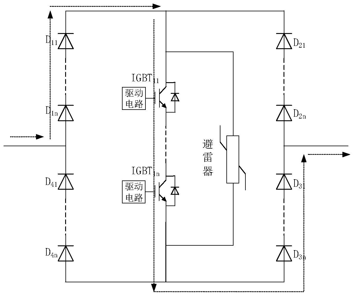
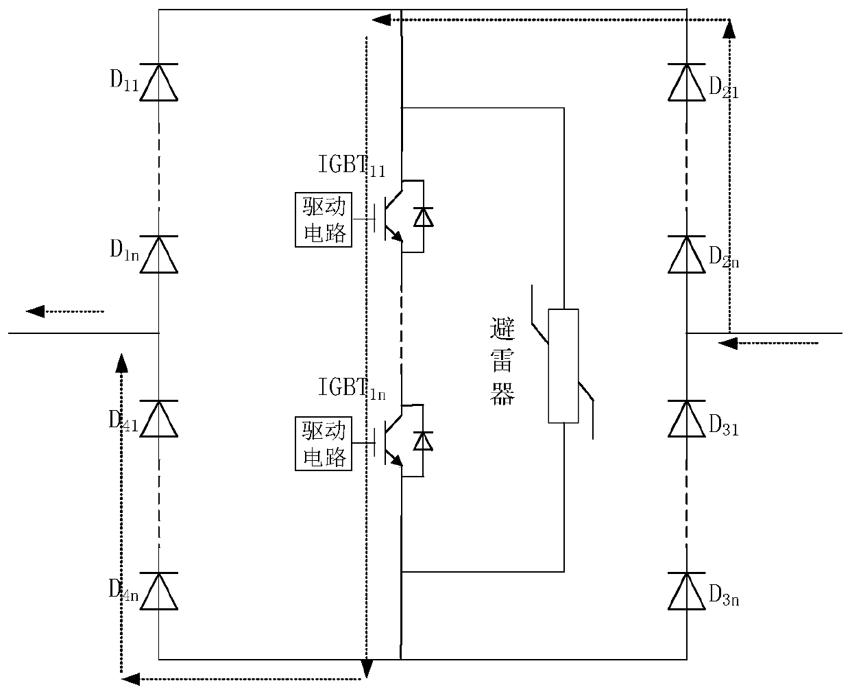
[0054] The invention provides a DC circuit breaker, which combines Figure 9 Introduce, including:

[0055] Parallel connected main current branch and transfer current branch;

[0056] The main flow branch includes: a series fast mechanical switch and a plurality of power electronic switches;

[0057] The transfer current branch includes a plurality of full-bridge modules connected in series;

[0058] Figure 6 It is a typical hybrid DC circuit breaker topology, which contains three parallel branches: the main flow branch, the transfer current branch and the energy absorption branch. Among them, the main current branch is composed of a fast mechanical switch K and an auxiliary converter module composed of a small number of power electronic switches in series to carry the rated current of the system during normal operation of the system; the transfer current branch is composed of a large number of power electronic switches in series for Break the short-circuit current of th...


PUM


Abstract

The invention provides a full-bridge module, which comprises a plurality of diodes, a plurality of full-control devices, a lightning arrester and a plurality of driving circuits, wherein the pluralityof diodes are connected in series to form a bridge structure, each full-control device is connected with a driving circuit, and after the plurality of full-control devices are connected in series, the full-control devices are connected with the lightning arrester in parallel, and then are connected to the midpoints of the upper bridge arm and the lower bridge arm of the bridge structure. According to the invention, by adopting the diodes connected in series, the full-bridge module reaches rated voltage and is prevented from being broken down; based on the diodes connected in series in a bridge mode, the number of the modules connected in series is remarkably reduced, and the equipment cost and size can be reduced; and the problem of series voltage sharing of full-control devices is solvedthrough effective cooperation of the drive circuit and the lightning arrester.

Description

technical field [0001] The invention belongs to the technical field of power electronics, and in particular relates to a full bridge module and a DC circuit breaker. Background technique [0002] With the application of multi-terminal flexible DC and DC grid technology based on voltage source converter (VSC), high-voltage DC circuit breakers have become one of the key equipment to ensure the stable, safe and reliable operation of the system. The DC circuit breaker technology that mixes mechanical switches and fully-controlled power electronic switches combines the low loss characteristics of mechanical switches and the fast breaking characteristics of power electronic switches. It is currently the most effective technical approach for DC breaking in high-voltage transmission systems. When high-voltage DC circuit breakers are applied to flexible multi-terminal DC and DC power grids with large capacity overhead lines, in addition to the characteristics of fast and low loss, th...

Claims


Application Information

Patent Timeline
Patent Type & Authority Applications(China)
IPC IPC(8): H02H7/26H01H9/54H03K17/51H03K17/08
CPCH01H9/542H01H9/547H01H9/548H01H2009/543H01H2009/544H02H7/268H03K17/08H03K17/51H03K2017/515
Inventor 单云海高冲周万迪庞辉魏晓光张升
Owner GLOBAL ENERGY INTERCONNECTION RES INST CO LTD
Why Eureka
Try Eureka