Small imaging device and zoom lens
A technology of zoom lens and camera device, which is applied in the field of photography, can solve the problems of increased camera thickness and reduced user experience, and achieve the effects of miniaturization, increased experience, and reduced moving range
- Summary
- Abstract
- Description
- Claims
- Application Information
AI Technical Summary
Problems solved by technology
Method used
Image

Examples
Embodiment 1
[0037] Embodiment one: if figure 1 with figure 2 As shown, a small camera device includes:
[0038] zoom lens;
[0039] and an image pickup element configured to receive an image formed by the zoom lens; the image pickup element is a CCD or a CMOS, and the image pickup element can be arranged on the image side IMG of the folding zoom optical lens.
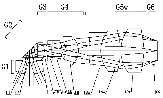
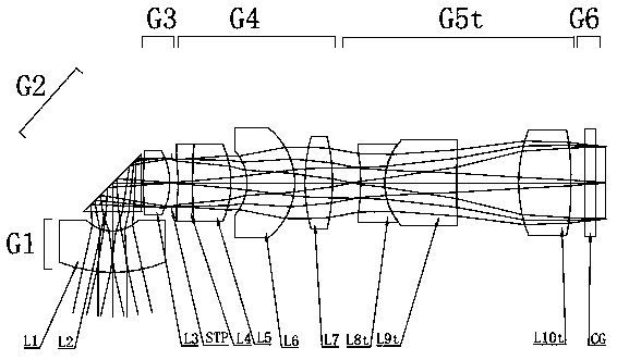
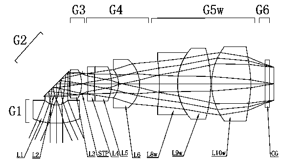
[0040] The zoom lens includes in order from the object plane side to the image plane side:
[0041] The front lens group G1, the reflection assembly G2, the first lens group G4 and the second lens group.
[0042] The reflection component G2 is used to reflect the light received by the front lens group G1 to the first lens group G4. Specifically, the reflection component G2 is mainly a component such as a reflection prism or a reflection plate that can greatly change the angle of the light.
[0043] The first lens group G4 moves along the optical axis of the zoom lens. In this embodiment, the first lens group G4 can move left and...
Embodiment 2
[0055] Embodiment two: if figure 1 with figure 2 As shown, a small camera device, the difference between this embodiment and the first embodiment lies in the specific parameters of the zoom lens.
[0056] On the basis of Embodiment 1, in this embodiment, the zoom lens satisfies the following conditional formula:
[0057] 3.9mm
[0058] f2max > 0;
[0059] 0.4
[0060] Wherein, f is the focal length of the zoom lens, f2max is the maximum focal length among the focal lengths of multiple second lens groups G5, D2max is the maximum optical total length among the multiple optical total lengths of the second lens group G5, TTL is the total optical length of the zoom lens.
[0061] In this embodiment, through the limitation of the above conditional formula, under the condition that the performance of the zoom lens is less affected, the total optical length of the second lens group G5 is reduced, which is beneficial to realize the miniaturization of the...
Embodiment 3
[0079] Embodiment three: as figure 1 with figure 2 As shown, a small camera device includes:
[0080] zoom lens;
[0081] and an image pickup element configured to receive an image formed by the zoom lens;
[0082] The zoom lens includes in sequence from the object plane side to the image plane side: a front lens group G1 with negative diopter power, a reflection assembly G2, an adjustment lens group G3 with positive diopter power, a stop STP, a first lens group G4 with positive diopter power, Second lens group and auxiliary component G6.
[0083] The front lens group G1 is the first lens L1 with negative refractive power.
[0084] The reflection component G2 is a prism, the prism is preferably a triangular prism, and the prism is used to reflect the light received by the front lens group G1 to the first lens group G4; the side of the prism facing the front lens group G1 is the incident surface, and the second prism faces the first lens group G4. One side of the lens gro...
PUM
 Abstract
Description
Claims
Application Information
 - R&D
- Intellectual Property
- Life Sciences
- Materials
- Tech Scout
- Unparalleled Data Quality
- Higher Quality Content
- 60% Fewer Hallucinations
Browse by: Latest US Patents, China's latest patents, Technical Efficacy Thesaurus, Application Domain, Technology Topic, Popular Technical Reports.
© 2025 PatSnap. All rights reserved.Legal|Privacy policy|Modern Slavery Act Transparency Statement|Sitemap|About US| Contact US: help@patsnap.com