Direction-adjustable self-closing pressure gauge valve

A pressure gauge and self-closing technology, which is applied in elastic deformation meter type fluid pressure measurement, fluid pressure measurement, fluid pressure measurement through mechanical components, etc., can solve the problems of inconvenient disassembly and assembly, reduce the possibility of rotation, reduce the Decrease in effect, increase in effect of sealing effect

Pending Publication Date: 2020-08-07
NANJING NAUTICAL INSTR PLANT NO 2
View PDF1 Cites 4 Cited by
  • Summary
  • Abstract
  • Description
  • Claims
  • Application Information

AI Technical Summary

Problems solved by technology

[0004] When the hydraulic steering gear in the prior art is used for a long time, when the pressure gauge is damaged, the pressure gauge needs to be replaced. At this time, the pressure gauge switch needs to be turned off to block the oil circuit before the pressure gauge can be disassembled. It is inconvenient to disassemble and assemble, and needs to be improved

Method used


Image

  • Direction-adjustable self-closing pressure gauge valve
  • Direction-adjustable self-closing pressure gauge valve
  • Direction-adjustable self-closing pressure gauge valve

Examples


Embodiment 1

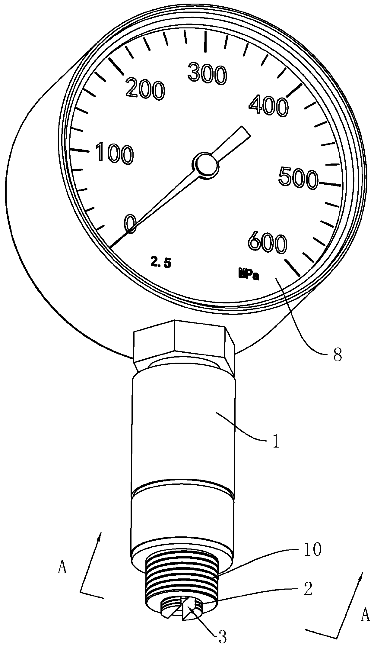
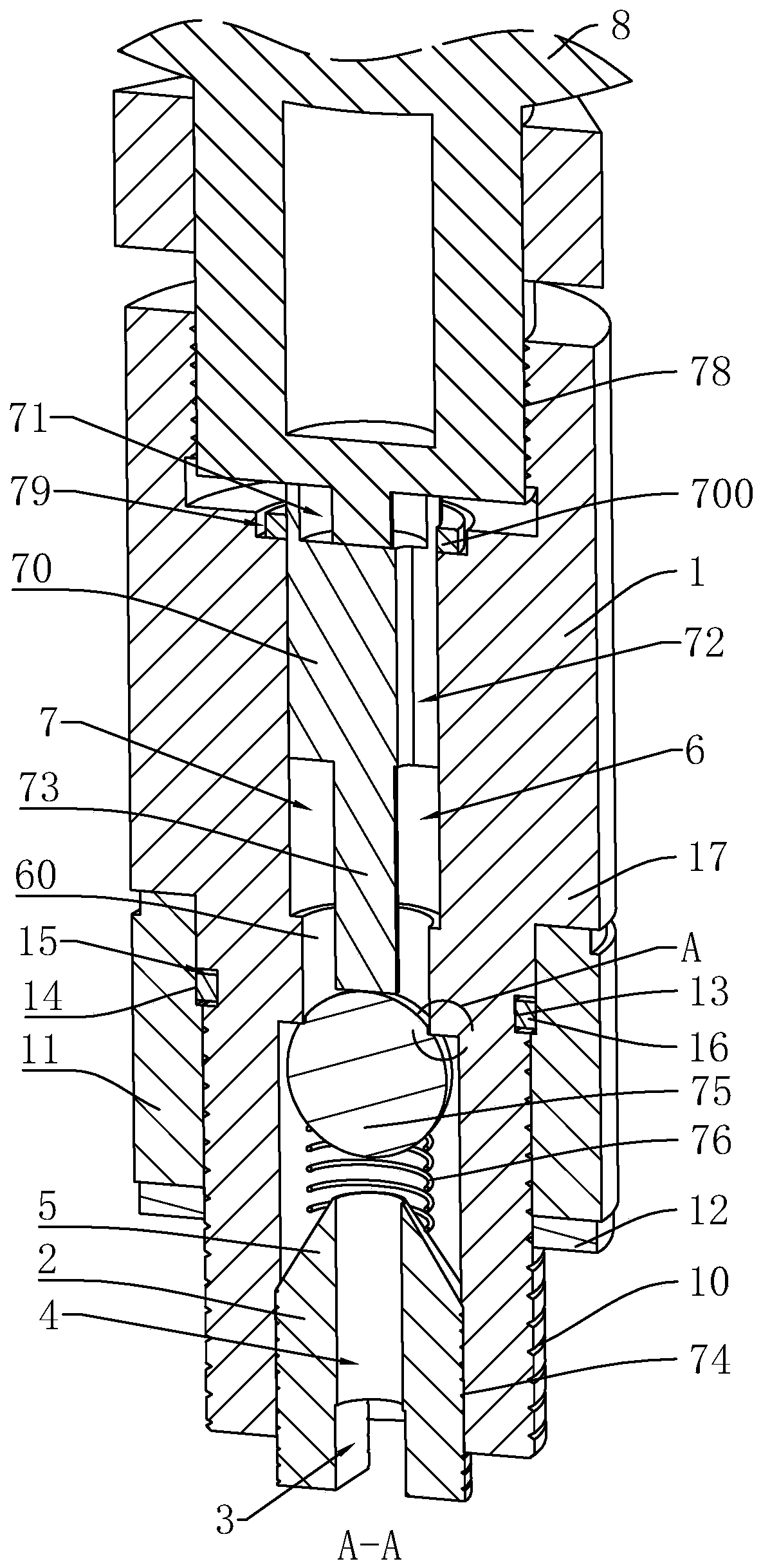
[0043] refer to figure 1 with figure 2 , an adjustable self-closing pressure gauge valve, which includes a cylinder 1, the outer wall of the cylinder 1 is provided with an external thread 10 screwed into the fuel tank, and the end of the cylinder 1 close to the fuel tank is threaded with a thimble 2, the cylinder 1 The end close to the fuel tank is threadedly connected with a thimble 2, the end of the thimble 2 away from the oil inlet 3 is provided with a tip 5, the end of the thimble 2 away from the tip 5 extends out of the cylinder 1, and the end of the thimble 2 protruding out of the cylinder 1 is provided with a The oil inlet 3 communicated with the oil tank, the thimble 2 is provided with a channel 4 communicated with the oil inlet 3 , and the barrel 1 is provided with a flow channel 6 communicated with the channel 4 .

[0044] refer to figure 2 , the tip 5 is sleeved with a self-closing component 7 for closing the flow channel 6, the self-closing component 7 slides i...

Embodiment 2

[0055] An adjustable self-closing pressure gauge with 8 valves, refer to Figure 4 with Figure 5 , based on Embodiment 1, the difference between this embodiment and Embodiment 1 is that the cylinder body 1 includes a fixed cylinder 18 connected to the pressure gauge 8 and a connecting cylinder 19 screwed to the fuel tank, and the fixed cylinder 18 is close to the connecting cylinder 19 One side is provided with a connecting ring groove 100, and the side of the connecting cylinder 19 close to the fixed cylinder 18 is provided with a ring piece 101 screwed into the connecting ring groove 100; it is convenient to connect the connecting cylinder 19 and the fixed cylinder 18.

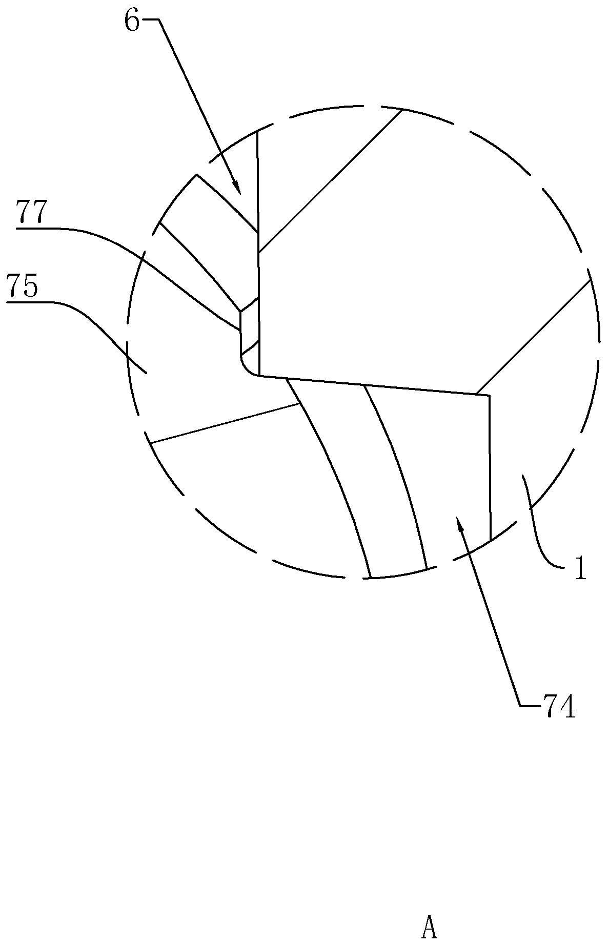
[0056] refer to Figure 5 with Image 6 , in the long-term use of the opening and closing ball 75, when the interference rod 73 squeezes the opening and closing ball 75, the opening and closing ball 75 is easy to rotate, and the junction corner between the annular groove 74 and the flow channel 6 is easy ...


PUM


Abstract

The invention discloses a direction-adjustable self-closing pressure gauge valve, relates to a pressure gauge, and aims at solving the technical problem that in the prior art, a pressure gauge is inconvenient to disassemble is solved. The key points of the technical scheme are that the device comprises a cylinder connected with an oil tank; an ejector pin is arranged at the end, close to the oil tank, of the cylinder; a through groove communicated with the oil tank is formed in the ejector pin, a flow channel communicated with the through groove is formed in the cylinder, the ejector pin is sleeved with a self-closing assembly used for closing the flow channel, and a pressure gauge used for driving the self-closing assembly to open the flow channel is connected to the side, away from the ejector pin, of the cylinder. When the pressure gauge needs to be disassembled, the pressure gauge is disassembled, the self-closing assembly is used for closing the flow channel and blocking flowing of hydraulic oil, a new pressure gauge is installed on the cylinder, the pressure gauge drives the self-closing assembly to open the flow channel, the hydraulic oil flows again, and use is reduced so that the pressure gauge can be disassembled and assembled conveniently and rapidly.

Description

technical field [0001] The present invention relates to a pressure gauge, more specifically, it relates to an adjustable self-closing pressure gauge valve. Background technique [0002] A pressure gauge refers to an instrument that uses elastic components as sensitive components to measure and indicate pressure higher than the environment. The conversion mechanism transmits the pressure deformation to the pointer, causing the pointer to rotate to display the pressure. This table can be seen everywhere in the fields of heat pipe network, oil and gas transmission, water supply and gas supply system, vehicle repair and maintenance shop and so on. [0003] The Chinese patent with the authorized announcement number CN201849659U discloses a marine hydraulic steering gear, including a power pump set composed of hydraulic pumps, a fuel tank, a low liquid level alarm installed on the fuel tank, an air filter and an oil return filter. device, pressure gauge, steering mechanism, trav...

Claims


Application Information

Patent Timeline
IPC IPC(8): G01L7/02G01L7/06G01L7/08G01L7/10G01L19/00F16K1/14
CPCF16K1/14G01L7/022G01L7/06G01L7/08G01L7/10G01L19/0015
Inventor 刘强丁汝森糜翔黄育青
Owner NANJING NAUTICAL INSTR PLANT NO 2
Why Eureka
Try Eureka