Combined gearbox

A gearbox and combined technology, applied in the field of gearboxes, can solve the problems of consumption, slow driving speed, complicated installation, etc., and achieve the effect of reducing the overall volume, reducing the consumption of materials, and changing the overall area.

Pending Publication Date: 2020-08-07
郭志强
View PDF0 Cites 0 Cited by
  • Summary
  • Abstract
  • Description
  • Claims
  • Application Information

AI Technical Summary

Problems solved by technology

[0003] In the existing gearbox, two gearboxes are connected in series, and the position of the input shaft of the second gearbox is unreasonably designed, resulting in shaft breakage. When the second gearbox bears a large load when reversing, the reverse gear teeth are knocked out. The fried shell only has reverse gear function in the second gearbox, and cannot restore the original speed ratio, making it drive slowly, which has no economic benefits. Because the second gearbox is bulky, complicated to install, and consumes more materials, it leads to an increase in manufacturing costs.

Method used


Image

  • Combined gearbox
  • Combined gearbox
  • Combined gearbox

Examples


Embodiment Construction

[0016] The technical solution of this patent will be further described in detail below in conjunction with specific embodiments.

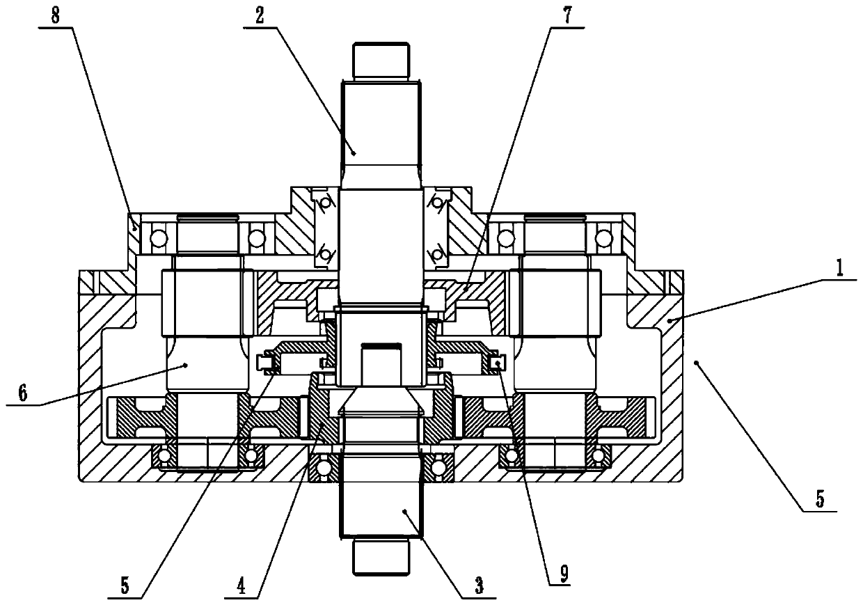
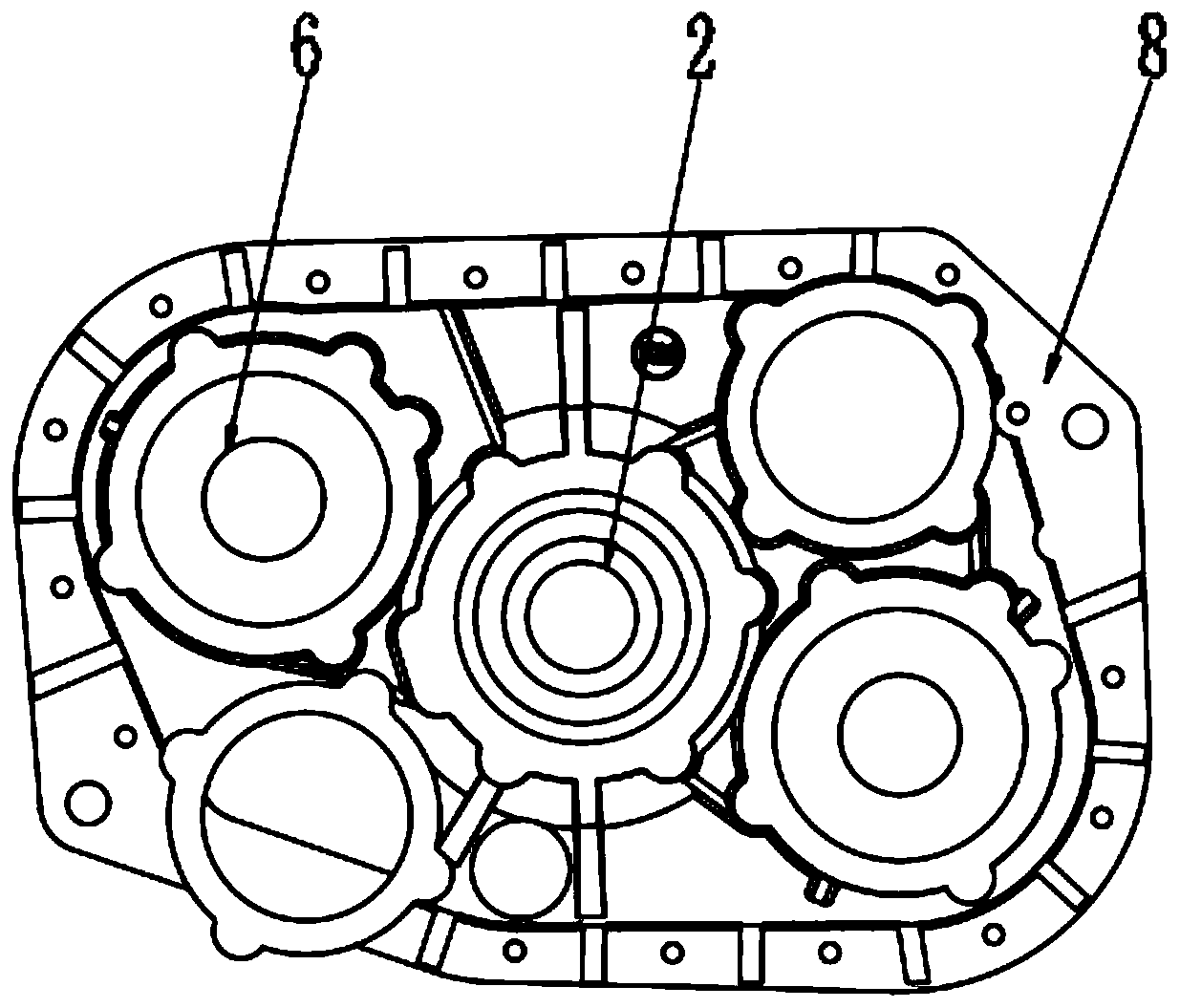
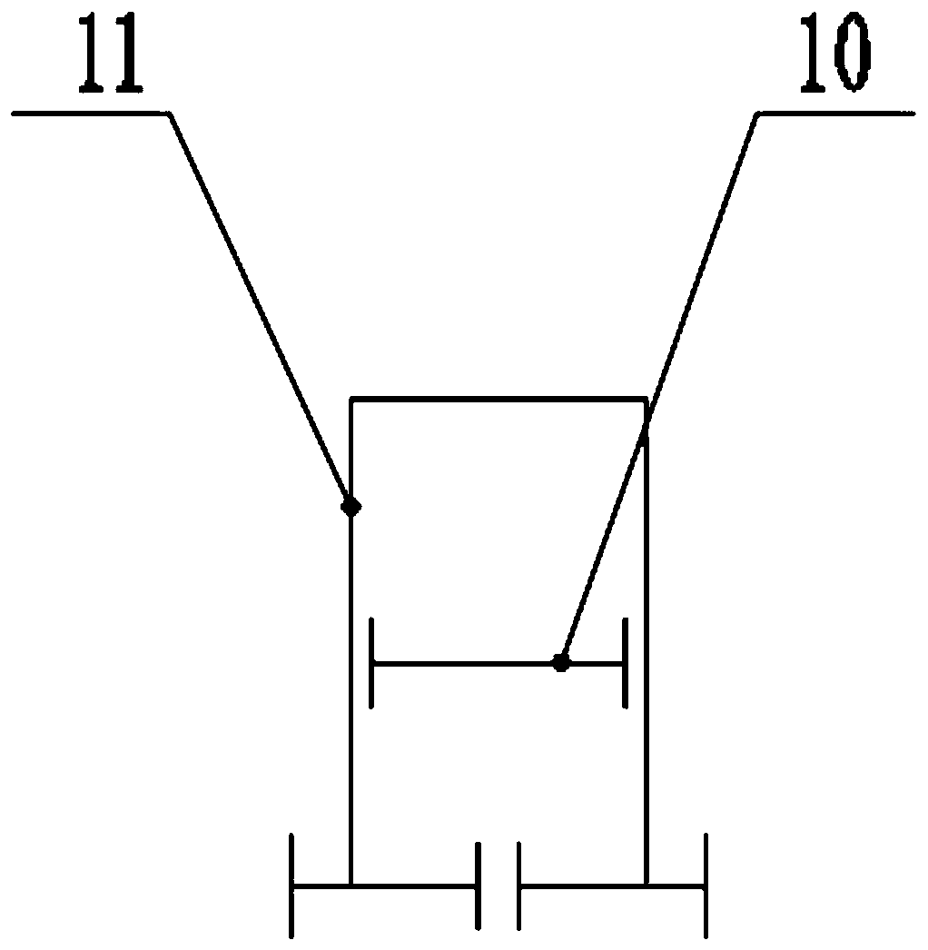
[0017] see Figure 1-3 , a combined gearbox, including a first box body 1, a welded shaft assembly 6 runs through the left and right sides of the first box body 1, an output shaft 2 is connected to the center of the top of the first box body 1, and the output shaft 2 The bottom speed gear 7 is connected between the outer surface of the outer surface and the two welded shaft assemblies 6, the top of the first case 1 is connected with the second case 8, the center of the bottom of the first case 1 is connected with the input shaft 3, and the input The top of the shaft 3 is clamped with the bottom of the output shaft 2, the outer surface of the input shaft 3 is sleeved with a high-speed gear 4, the outer surface of the output shaft 2 is sleeved with a sliding sleeve 5, and the outer surface of the sliding sleeve 5 is clamped with a fork 9. The fork 9...


PUM


Abstract

The invention discloses a combined gearbox. The combined gearbox comprises a first box body, wherein the center of the top of the first box body is connected with an output shaft, the center of the bottom of the first box body is connected with an input shaft, the top of the input shaft is in clamped connection with the bottom of the output shaft, the outer surface of the input shaft is sleeved with a high-speed gear, and the outer surface of the output shaft is sleeved with a sliding sleeve. According to the combined gearbox, the problem of shaft breakage caused by unreasonable position design of an input shaft of a second gearbox body is avoided, and the problem of tooth beating is solved to a great extent. The problems that the second gearbox body only has a reverse gear function, the driving speed is low, and labor hours are wasted are solved, the overall size of the gearbox is changed, and the combined gearbox solves the problem of gearbox shaft breakage and tooth breaking to a great extent. The gearbox has double speed ratios and can advance and retreat, the speed can be high, labor hours are saved, labor is saved, the speed can also be low, stable beam conveying is achieved,the overall size is reduced, material consumption is reduced, and the cost is reduced. The beam conveying gearbox truly saves time, labor and money.

Description

technical field [0001] The invention relates to the technical field of gearboxes, in particular to a combined gearbox. Background technique [0002] The gearbox mainly refers to the gearbox of the car, which is divided into manual and automatic. The manual gearbox is mainly composed of gears and shafts, and the variable speed and torque are generated through different gear combinations; It is composed of torque converter, planetary gear, hydraulic pitch change system and hydraulic control system. Variable speed and torque are achieved through hydraulic transmission and gear combination. [0003] In the existing gearbox, two gearboxes are connected in series, and the position of the input shaft of the second gearbox is unreasonably designed, resulting in shaft breakage. When the second gearbox bears a large load when reversing, the reverse gear teeth are knocked out. The fried shell only has reverse gear function in the second gearbox, and cannot restore the original speed ...

Claims


Application Information

Patent Timeline
Patent Type & Authority Applications(China)
IPC IPC(8): F16H3/097F16H57/02F16H57/023
CPCF16H3/097F16H57/02F16H57/023F16H2057/02043F16H2057/02086
Inventor 郭志强
Owner 郭志强
Why Eureka
Try Eureka