Protective shed of construction site distribution box

A technology for construction sites and distribution boxes, applied in earthquake-proof, special buildings, small buildings, etc., can solve problems such as high cost, damage to distribution boxes, safety accidents, etc., achieve good rigidity and stability, and eliminate shocks. The effect of energy, good anti-collision ability

Inactive Publication Date: 2020-08-07
合肥立达电气有限公司
View PDF0 Cites 3 Cited by
  • Summary
  • Abstract
  • Description
  • Claims
  • Application Information

AI Technical Summary

Problems solved by technology

When the protective shed in the prior art is subjected to a large mechanical impact on the construction site, the structure will be seriously damaged, which will easily lead to damage to the distribution box and cause a safety accident. At t

Method used


Image

  • Protective shed of construction site distribution box
  • Protective shed of construction site distribution box
  • Protective shed of construction site distribution box

Examples


Embodiment 1

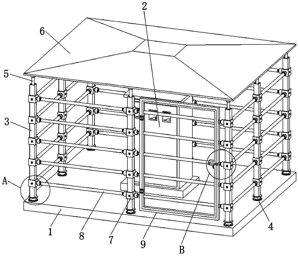
[0036] like Figure 1-Figure 8 As shown, a first embodiment of the protection shed for the distribution box at the construction site of the present invention is provided. The upper end of the foundation 2 is located on the peripheral side of the distribution box 1, and the bottom end of the column rod 3 is fixed with a rubber support 4, wherein the rubber support 4 includes a rubber column 401, and a ring-shaped steel plate 402 layered and fixed in the rubber column 401 , the upper connecting steel plate 403 fixed on the upper end of the rubber column 401 and the lower connecting steel plate 404 fixed on the lower end of the rubber column 401, the upper connecting steel plate 403 is fixed on the lower end of the column rod 3, and the lower connecting steel plate 404 is connected with a pre-embedded steel foot 10 by bolts , the pre-embedded steel feet 10 can be used for one-time construction without recycling, which is convenient for the disassembly and assembly of the column r...

Embodiment 2

[0046] like Figure 9 As shown, a second embodiment of the protection shed for the distribution box at the construction site of the present invention is provided. The difference from the first embodiment is that the energy dissipation structure in the buffer hole 301 is an energy dissipation spring 12, and the energy dissipation The spring 12 is set between the buffer rod 5 and the inner wall of the buffer hole 301, the energy dissipation spring 12 provides the upward support force of the buffer rod 5, and the inner wall of the upper end of the buffer hole 301 is fixed with a limit ring, which limits the maximum upward stroke of the buffer rod 5 , The energy-dissipating spring 12 can also play the role of energy-dissipating and shock-absorbing, and provides impact protection for the ceiling 6 .


PUM


Abstract

The invention discloses a protective shed of a construction site distribution box. The protective shed of the construction site distribution box comprises a concrete foundation fixedly provided with the distribution box and further comprises stand column rods, a canopy, a fence and a safety door. Wherein the stand column rods are vertically installed at the upper end of the concrete foundation andlocated on the periphery of the distribution box, the bottom ends of the stand column rods are fixedly provided with rubber support seats, the upper end of each stand column rod is provided with a buffering hole, buffering rods are connected into the buffering holes through energy dissipating structures, the canopy is in spherical hinge connection with the upper ends of the buffering rods on thestand column rods, the fence is formed by connection pieces and cross rods, the connection pieces are fixed at intervals in the length direction of the stand column poles, the two ends of each cross rod are in spherical hinge connection with the two connection pieces of the adjacent stand column poles, and the two sides of the safety door are in spherical hinge connection with the connection pieces on the two adjacent stand column poles. When the overall protective shed bears impact, impact energy can be eliminated through shaking, the rigidity and stability of the framework of the protectiveshed are good, and therefore under the condition that the protective shed is not prone to damage or deformation, the protective shed has better anti-collision capacity.

Description

technical field [0001] The invention belongs to the technical field of distribution box protection sheds, in particular to a construction site distribution box protection shed. Background technique [0002] "Electricity" is an indispensable energy source in people's production and life. "Electricity" is also a major source of danger in construction sites. However, many construction sites have weak links in "safe use of electricity", which leads to outages. Electricity, electric shock and other production safety accidents. For the smooth progress of the project, temporary distribution boxes will be installed around the construction site. In order to ensure the safety of electricity use on the construction site and prevent electric shock accidents, the temporary distribution boxes installed on the construction site must be installed with protective sheds. [0003] The purpose of the distribution box protective shed is to protect the primary and secondary distribution boxes on...

Claims


Application Information

Patent Timeline
IPC IPC(8): E04H1/12E04B1/24E04B1/58E04B1/98
CPCE04B1/2403E04B1/5825E04B1/98E04B2001/2406E04H1/1238
Inventor 黄立耕李大钧陶恩正张世安周磊陈常松
Owner 合肥立达电气有限公司
Why Eureka
Try Eureka