Displacement self-compensation damping mechanism of draw bar and hoisting structure of superconducting magnet

A vibration-damping mechanism and self-compensating technology, applied in superconducting magnets/coils, shock absorbers, magnetic objects, etc., to avoid resonance and reduce positioning accuracy requirements

Inactive Publication Date: 2015-04-29
INST OF HIGH ENERGY PHYSICS CHINESE ACAD OF SCI
View PDF5 Cites 3 Cited by
  • Summary
  • Abstract
  • Description
  • Claims
  • Application Information

AI Technical Summary

Problems solved by technology

[0005] In the existing technology, many inventions about superconducting magnet tie rods are disclosed, but there is no research related to the vibration reduction of superconducting magnet tie rods

Method used


Image

  • Displacement self-compensation damping mechanism of draw bar and hoisting structure of superconducting magnet
  • Displacement self-compensation damping mechanism of draw bar and hoisting structure of superconducting magnet
  • Displacement self-compensation damping mechanism of draw bar and hoisting structure of superconducting magnet

Examples


Embodiment Construction

[0029] Typical embodiments embodying the features and advantages of the present invention will be described in detail in the following description. It should be understood that the invention is capable of various changes in different embodiments without departing from the scope of the invention, and that the description and illustrations therein are illustrative in nature and not limiting. this invention.

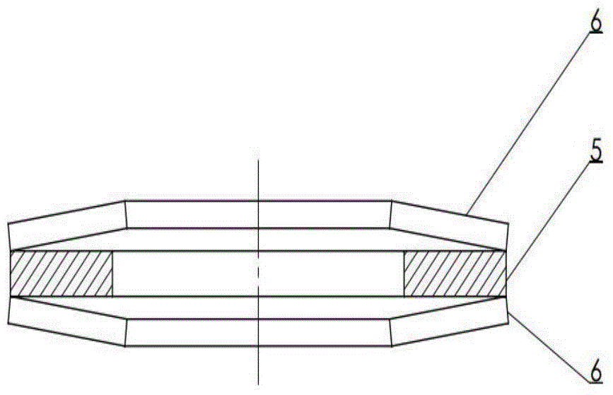
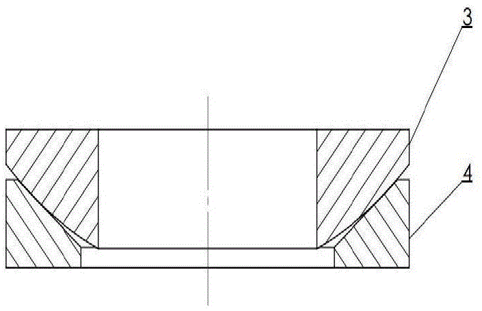
[0030] figure 1 Shown is an embodiment of the present invention, a displacement self-compensating vibration damping mechanism for a superconducting magnet tie rod, installed between a superconducting magnet tie rod end fixing part and a pressure-bearing part, and the pressure-bearing part bears tension at the end of the tie rod , the vibration damping mechanism includes two pressure bearing pads and a plurality of elastic damping units located between the two pressure bearing pads; in the specific embodiment, the bottom is a deflection adjustment unit (which can be a joint...


PUM


Abstract

The invention discloses a displacement self-compensation damping mechanism of a draw bar and a hoisting structure of a superconducting magnet. A washer is clamped between every two pairwise opposite dish gaskets to form a vibration attenuation unit, and the actual mechanism is generally formed by the fact that a plurality of vibration attenuation units are overlapped. Spherical surface gaskets and conical surface gaskets form a displacement self-compensation deflation regulation unit, and the actual mechanism generally comprises a plurality of deflation regulation units. The displacement self-compensati0on damping mechanism is formed by the fact that a plurality of vibration attenuation units and a plurality of deflation regulation units are combined and overlapped at will. The displacement self-compensation damping mechanism is cooperated with the draw bar of the superconducting magnet, can effectively perform a vibration attenuation function in a transportation process of the superconducting magnet and lowers requirements on positioning precision when the draw bar is installed. When the vibration attenuation units incline to one side or do not have the same axis, the deflation regulation units can perform a displacement compensation function and can keep a large pressure contact area so as to effectively avoid stress concentration, and one part of thermal contraction stress of the draw bar of the superconducting magnet can be compensated.

Description

technical field [0001] The invention relates to a superconducting magnet fixing technology, belongs to the application field of superconducting magnet technology, and is applied to a superconducting magnet pull rod connecting a high temperature end and a low temperature end. Background technique [0002] At present, superconducting magnets have entered large-scale commercial applications, such as MRI, superconducting magnetic separation, superconducting iron remover, etc. The interior of a superconducting magnet generally includes a low-temperature Dewar, a heat radiation shield, and a vacuum container, and the connection between these devices is mainly completed by tie rods. [0003] In superconducting magnets, the design of tie rods is generally an important part of the magnet design. Considering the heat leakage of the magnet caused by the tie rod and the structural strength of the tie rod, generally, the cross-sectional area of ​​the tie rod should not be too large, and...

Claims


Application Information

Patent Timeline
Patent Type & Authority Applications(China)
IPC IPC(8): F16F7/00H01F6/00
CPCF16F7/00H01F6/00
Inventor 张恺朱自安侯治龙赵玲
Owner INST OF HIGH ENERGY PHYSICS CHINESE ACAD OF SCI
Why Eureka
Try Eureka