Metal part cutting device

A cutting device and metal parts technology, applied in the field of metal parts cutting, can solve the problems of the spherical body of the cutting blade, the lack of dimensional accuracy, and the difficulty in regulating the cutting spherical surface, and achieve the effects of improving applicability, dimensional accuracy and surface smoothness.

Inactive Publication Date: 2020-08-07
亳州专海智能科技有限公司
View PDF11 Cites 3 Cited by
  • Summary
  • Abstract
  • Description
  • Claims
  • Application Information

AI Technical Summary

Problems solved by technology

[0004] The invention provides a metal part cutting device, which has the advantages of improving the dimensional accuracy of the metal part cutting device for cutting spherical parts and improving the applicability of the metal part cutting device for cutting spherical parts, and solves the problem of existing spherical parts. During processing, a cutting tool is usually used to rotate the corresponding cutting part at a fixed point to cut it. At the same time, it is necessary to rotate the cutting blade and keep the running distance of the cutting piece at the diameter of the spherical surface, and it is difficult to control the cutting through a cutting tool during the installation process. The radius of the spherical surface is likely to be a cutting blade and the eliminated spherical body does not reach the preset dimensional accuracy, causing the dimensional accuracy of the star parts at the cutting place to be less than the table, and the surface quality is unqualified.

Method used


Image

  • Metal part cutting device
  • Metal part cutting device
  • Metal part cutting device

Examples


Embodiment Construction

[0021] The following will clearly and completely describe the technical solutions in the embodiments of the present invention with reference to the accompanying drawings in the embodiments of the present invention. Obviously, the described embodiments are only some, not all, embodiments of the present invention. Based on the embodiments of the present invention, all other embodiments obtained by persons of ordinary skill in the art without making creative efforts belong to the protection scope of the present invention.

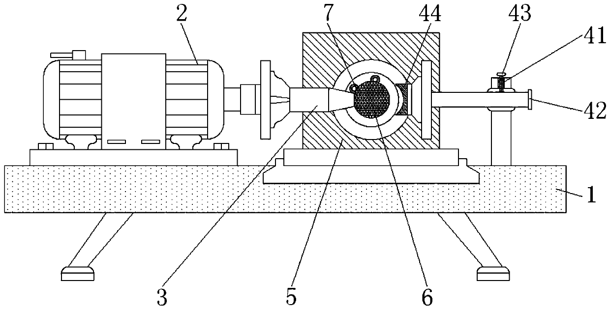
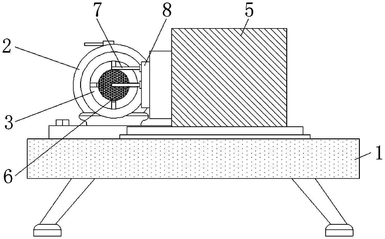
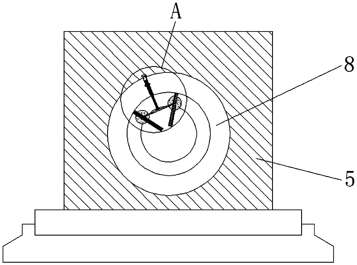
[0022] see Figure 1-5 , a metal part cutting device, comprising an operating table 1, a servo motor 2 is fixedly installed on the left side of the upper surface of the operating table 1, and a control device 4 is fixedly connected to the right side of the upper surface of the operating table 1, and the servo Between the motor 2 and the regulating device 4, there is a table turning device 5. The table turning device 5 realizes the forward and reverse rotation ...


PUM


Abstract

The invention relates to the technical field of metal part cutting, and discloses a metal part cutting device. The metal part cutting device comprises an operation table, wherein a servo motor is fixedly installed on the left side of the upper surface of the operation table, a regulation and control device is fixedly connected to the right side of the upper surface of the operation table, a tablerotating device is arranged between the servo motor and the regulation and control device, the bottom of the table rotating device is connected with the upper surface of the operation table in a clamped mode, and a conical fixing column is fixedly connected to an output shaft of the servo motor. Through cooperation between two cutting tools and a fixing disc, a mode that three points determine a circle is used, whether the radius length of a cut sphere of the cutting tools is consistent or not is checked conveniently, the included angles between the two cutting tools and the spherical centersof the two cutting tools are half of the horizontal included angle of metal with the cutting spherical shape, whether two cut hemisphere interfaces coincide or not is checked conveniently, and meanwhile, cutting is carried out by two cutting blades at the same time, and the size precision and the surface smoothness of a spherical part cut by the metal part cutting device are conveniently improved.

Description

technical field [0001] The invention relates to the technical field of metal part cutting, in particular to a metal part cutting device. Background technique [0002] Metal cutting is a method of material removal and forming in the metal forming process. It still occupies a large proportion in today's mechanical manufacturing. The metal cutting process is a process of interaction between the workpiece and the tool. The tool removes excess metal from the workpiece to be processed. And under the premise of controlling productivity and cost, the workpiece can obtain the geometric accuracy, dimensional accuracy and surface quality that meet the design and process requirements. In order to achieve this process, there must be relative motion between the workpiece and the tool, that is, cutting motion, metal cutting The device is a device that removes excess metal from metal blanks or semi-finished products and makes corresponding mechanical parts by means of cutting and special pr...

Claims


Application Information

Patent Timeline
Patent Type & Authority Applications(China)
IPC IPC(8): B23B5/40B23B25/06B23Q11/00
CPCB23B5/40B23B25/06B23B2270/30B23Q11/0064
Inventor 郑旭岳
Owner 亳州专海智能科技有限公司
Why Eureka
Try Eureka