
Phased-array antenna calibration method based on difference beam calibration

A phased array antenna and calibration method technology, which is applied in receiver monitoring, transmitter monitoring, etc., can solve the problems of calibration accuracy, alignment accuracy limitation, and limited use range, etc., to achieve small calculation, wide use range, and high engineering value effect

Active Publication Date: 2020-08-04
SHANGHAI RADIO EQUIP RES INST
View PDF9 Cites 7 Cited by
  • Summary
  • Abstract
  • Description
  • Claims
  • Application Information

AI Technical Summary

Problems solved by technology

Patent "A Phased Array Antenna Multi-beam Automatic Calibration Device and Its Automatic Calibration Method" (Patent Application No.: CN201510051961.X, Patent Publication No.: CN104597433A) In order to realize automatic calibration, when establishing the normal beam database 3, it is necessary to Under field conditions, the normal beams in each working mode of the phased array antenna are calibrated one by one, and the calibration accuracy is limited by the alignment accuracy of the auxiliary antenna and the antenna under test
The patent "A Method for Calibrating Amplitude and Phase of a Receive Channel in a Phased Array System" (patent application number: CN201010252906.4, patent publication number: CN101938305A) provides a method for calibrating the amplitude and phase of a receiving channel in a phased array system. The amplitude and phase errors of the receiving channel are well controlled, but the calibration source of the beamforming network is required, and the scope of use is limited

Method used


Image

  • Phased-array antenna calibration method based on difference beam calibration
  • Phased-array antenna calibration method based on difference beam calibration
  • Phased-array antenna calibration method based on difference beam calibration

Examples


Embodiment Construction

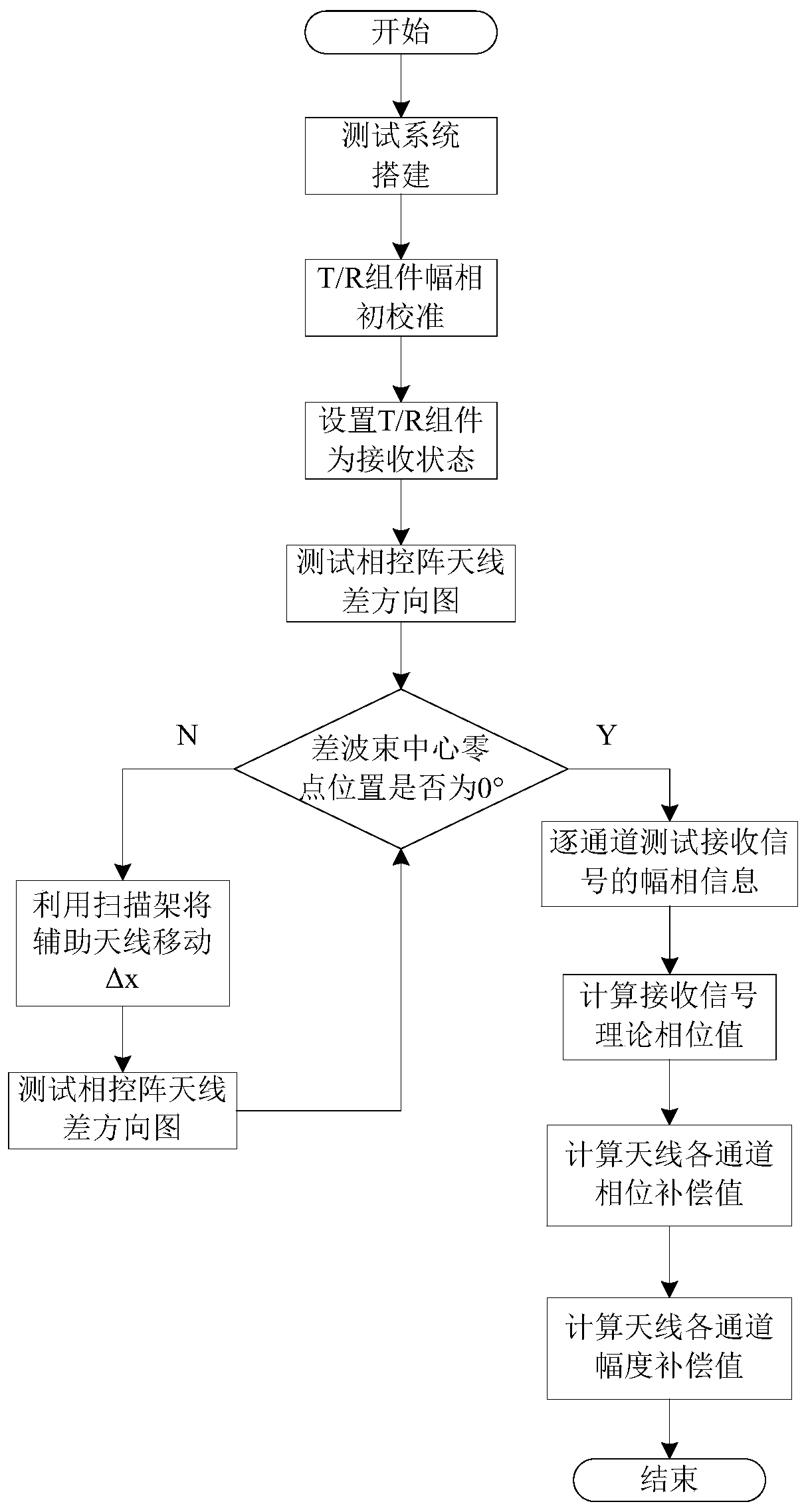
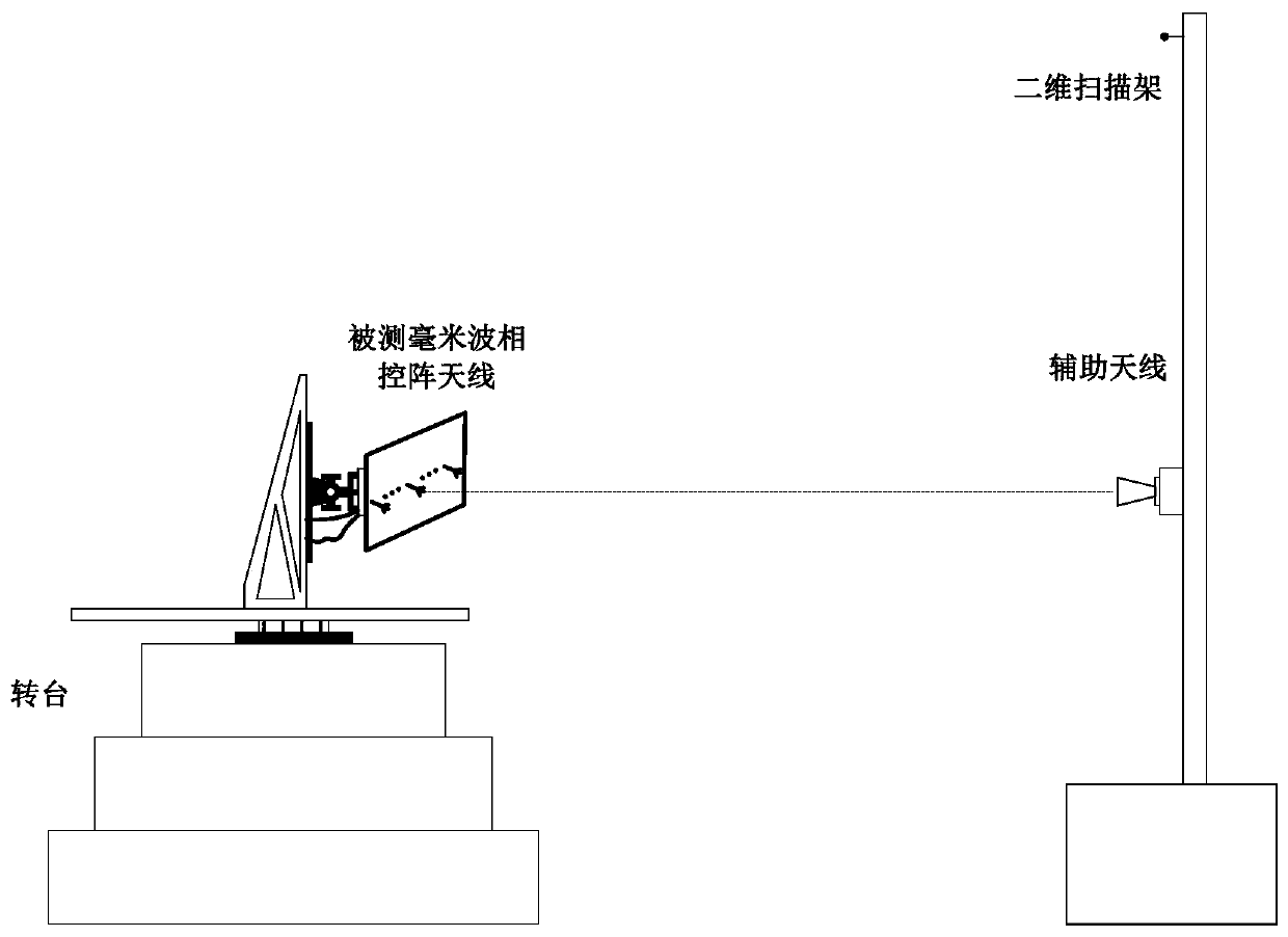
[0036] based on the following Figure 1 to Figure 5 , specifically explain the preferred embodiment of the present invention.

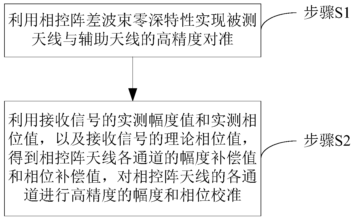
[0037] Such as figure 1 As shown, the present invention provides a phased array antenna calibration method, comprising the following steps:

[0038] Step S1, using the phased array differential beam zero-depth characteristic to achieve high-precision alignment between the measured phased array antenna and the auxiliary antenna, breaking the bottleneck of limited calibration accuracy of the phased array antenna;

[0039] Step S2, using the measured amplitude value and phase value of the received signal, and the theoretical phase value of the received signal to obtain the amplitude compensation value and phase compensation value of each channel of the phased array antenna, and perform high-precision The accurate amplitude and phase calibration can eliminate the influence of factors such as the assembly of the phased array antenna, the mutual coupling ...


PUM


Abstract

The invention discloses a phased-array antenna calibration method based on difference beam calibration. High-precision alignment of the measured phased-array antenna and the auxiliary antenna is realized by utilizing the zero-depth characteristic of a phased-array difference beam to obtain the secondary amplitude compensation value and the secondary phase compensation value of each channel of thephased-array antenna by utilizing the actually measured amplitude value and the actually measured phase value of the received signal and the theoretical phase value of the received signal, and high-precision amplitude and phase calibration is performed on each channel of the phased-array antenna. According to the midfield test method for performing high-precision calibration on the phased-array antenna by utilizing the zero-depth characteristic of the difference beam, the high-precision alignment of the auxiliary antenna and the tested antenna can be realized, no fitting error exists, and a high-precision calibration result can be obtained. Besides, the method can be carried out in the dark room all day long without meeting far-field conditions, auxiliary test equipment such as a total station is not needed, and the method has very high operability and relatively high engineering value.

Description

technical field [0001] The invention relates to the aerospace field, in particular to a field test method for high-precision calibration of a phased array antenna by using the zero-depth characteristic of a difference beam, which can be applied to the field of amplitude and phase calibration of a phased array antenna unit. Background technique [0002] In the aspects of phased array radar antenna array, mechanical processing and assembly of T / R components, affected by factors such as technological level, processing capacity and mutual coupling of T / R component units, after the antenna assembly is completed, each channel There will be certain inconsistencies in power, frequency spectrum, and amplitude and phase. The amplitude and phase distribution of the antenna array unit deviates from the design value, resulting in a decrease in the phased array radar antenna zero depth, main and side lobe ratio and other indicators. In order to meet the design requirements, the amplitude ...

Claims


Application Information

Patent Timeline
IPC IPC(8): H04B17/11H04B17/12H04B17/21
CPCH04B17/11H04B17/12H04B17/21
Inventor 焦美敬江利中邹波李雁斌谭姗姗黄勇杨明远
Owner SHANGHAI RADIO EQUIP RES INST
Learn More