
Non-contact mirror spacing measurement method based on matrix optics calculation

A non-contact, optical computing technology, which is applied in the direction of optical instrument testing, measuring devices, testing optical performance, etc., can solve the problems of unsatisfactory lens surface measurement, limit the practicality of interval measuring instruments, etc., achieve the realization of equipment application range, improve The effect of work efficiency and precision

Active Publication Date: 2021-09-07
CHANGCHUN JINGYI PHOTOELECTRIC TECH CO LTD
View PDF9 Cites 0 Cited by
  • Summary
  • Abstract
  • Description
  • Claims
  • Application Information

AI Technical Summary

Problems solved by technology

[0004] If there is no operation function of intelligent analysis, the selection of position parameters is made by the testers after repeated attempts, and finally determined based on experience. When the number of mirrors increases, it is difficult for testers to find suitable position parameters. It is possible to obtain all lens surfaces at one time and return Based on this empirical method, the maximum number of surfaces that can be measured at one time is about 8-10 pieces, which greatly limits the practicability of the interval measuring instrument
[0005] For example, the number of mirrors in the lithography machine system is mostly more than 10 pieces. Based on the empirically determined position parameter measurement scheme, multiple measurements are often required, and for some lens surfaces (such as glued surfaces), unsatisfactory results may occur. The intelligent analysis function of position parameters is particularly important

Method used


Image

  • Non-contact mirror spacing measurement method based on matrix optics calculation
  • Non-contact mirror spacing measurement method based on matrix optics calculation
  • Non-contact mirror spacing measurement method based on matrix optics calculation

Examples


Embodiment Construction

[0050] The present invention provides an optical calculation based on a matrix of non-contact method of measuring specular interval, visible light optical system for any test can be performed intelligently calculated mirror position parameters.

[0051] Selecting a bundle of packed standard lens, for example, contains the standard lens surface of the lens 20, based on the particular embodiment of the present invention is as follows.

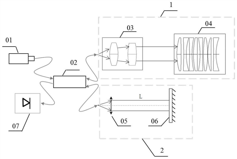
[0052] like figure 1 , The measuring principle of the non-contact distance measuring instrument specular follows: using super luminescent diode light source 01, the light emitted super luminescent diode 01 is a fiber coupler 02 into two parts, 1 all the way into the measurement arm, the light from the measuring head a collimator 03, and reflected by the surface of each lens tested lens group 04, and then return to the fiber coupler 02; all the way into the reference arm 2, comprising a delay line L, a collimator lens 05 by the light collimated by the...


PUM


Abstract

The invention relates to a non-contact mirror distance measurement method based on matrix optical calculation. The method is as follows: using a detector to detect the interference signal of two reflected lights; determining the position parameter candidate area in the optical path of the measuring arm; Determine the optimum position parameter for measuring the lens group under test and measure the thickness of all lenses in the lens group under test and the air gap on the surface under the position parameter. The present invention can automatically and quickly find out the best measurement head lens spacing and working distance for the interval measurement of the visible light optical system with any number of mirrors, and can balance the energy of all the mirrors to be measured to maximize the interval measurement work. efficiency and precision.

Description

Technical field [0001] The present invention belongs to the technical field of optical adjusting means, involving a non-contact measuring method for specular mirror spacing interval measuring instrument. Background technique [0002] The optical assembly and adjustment ring as a final lens produced through strict control of the mirror and the center deviation of the optical lens interval, to ensure that one of the key performance optical lens. In addition, the assembled optics verification interval to detect a problem is often encountered in the optical art. Non-contact distance measuring device based on the specular low coherence interferometry can dispatch personnel to assist loading intervals measured in real-time monitoring lens mounting process may be carried out precise measurement of the interval of the finished optics. Compared with classic laser interferometer, the low coherence interferometer advantages with respect to environmental disturbances have better robustness, ...

Claims


Application Information

Patent Timeline
Patent Type & Authority Patents(China)
IPC IPC(8): G01M11/02
CPCG01M11/0221G01M11/0271
Inventor 罗晓霞孙金霞孙强赵建
Owner CHANGCHUN JINGYI PHOTOELECTRIC TECH CO LTD
Learn More