Lifting appliance for rapidly lifting annular workpieces and lifting method
A technology of annular workpiece and spreader, which is applied in the field of lifting and transferring annular workpieces, can solve problems such as detachment, and achieve the effects of rapid detachment, rapid detachment and convenient operation.
- Summary
- Abstract
- Description
- Claims
- Application Information
AI Technical Summary
Problems solved by technology
Method used
Image
Examples
Embodiment 1
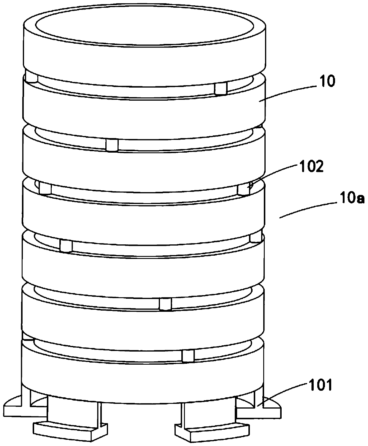
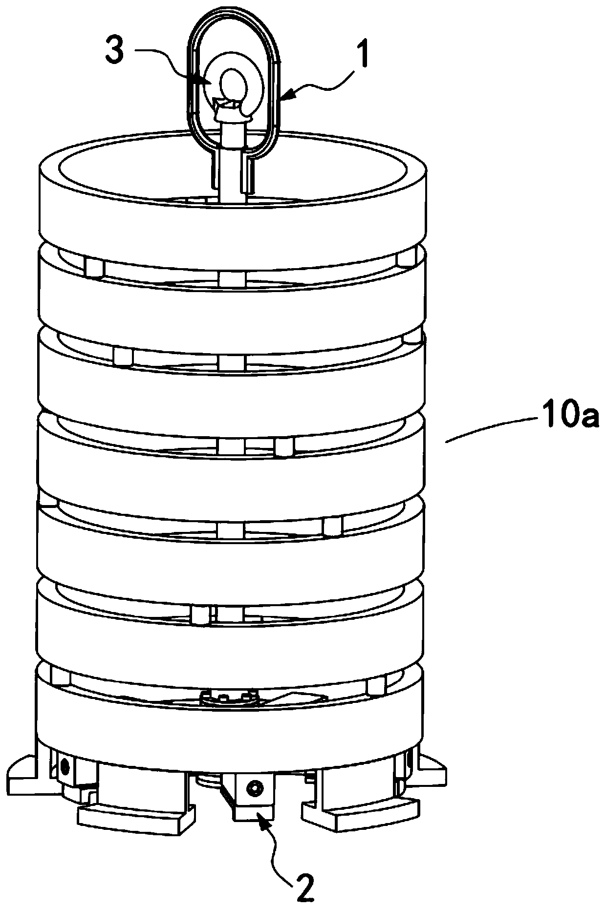
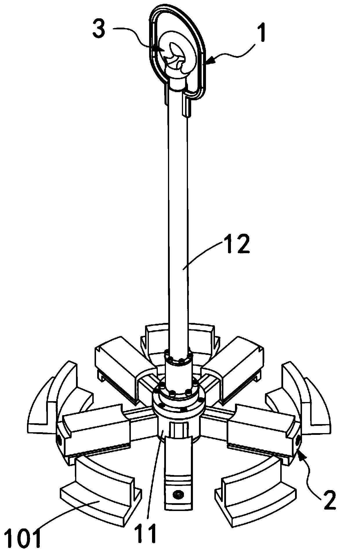
[0058] Such as Figure 1 to Figure 4 As shown, a ring-shaped workpiece fast hoisting sling is used for hoisting and transferring a pile 10a composed of a plurality of ring-shaped workpieces 10 stacked coaxially, including:
[0059] The outer spreader set 1, the outer spreader set 1 includes a spreader main body 11 and an outer lifting shaft unit 12, the spreader main body 11 is connected to the lower part of the outer lifting shaft unit 12, the spreader main body 11 It includes a cylindrically arranged sleeve portion 111 and a plurality of slide rail portions 112 equidistantly arranged along the circumferential direction of the sleeve portion 111, and the length direction of the slide rail portions 112 is all along the radial direction of the sleeve portion 111. set up;
[0060] The mobile support mechanism 2 is slidably installed on the lengthwise direction of the corresponding slide rail part 112 through a slider 21, and the end of the slider 21 pointing to the shaft center...
Embodiment 2
[0067] Figure 4 It is a schematic structural view of Embodiment 2 of a ring workpiece fast hoisting sling of the present invention; as Figure 4 As shown, the components that are the same as or corresponding to those in Embodiment 1 use the reference numerals corresponding to Embodiment 1. For the sake of simplicity, only the differences from Embodiment 1 will be described below. The Example 2 with figure 1 Example 1 shown differs in that:
[0068] Such as Figure 4 As shown, the outer lifting shaft unit 12 includes:
[0069] Lifting sleeve 121, the interior of the lifting sleeve 121 is hollow, for the insertion of the inner spreader group 3, and the upper end of the lifting sleeve 121 is provided with an outer suspension ring 122;
[0070] The spreader spring sleeve 123, the spreader spring sleeve 123 is coaxially connected and arranged on the lower end of the lifting sleeve 121; and
[0071] The spreader limit sleeve 124, the spreader limit sleeve 124 is coaxially arra...
Embodiment 3
[0076] Figure 5 It is a schematic structural view of Embodiment 3 of a ring workpiece fast hoisting sling of the present invention; as Figure 5 As shown, the components that are the same as or corresponding to those in Embodiment 1 use the reference numerals corresponding to Embodiment 1. For the sake of simplicity, only the differences from Embodiment 1 will be described below. The Example 3 with figure 1 Example 1 shown differs in that:
[0077] Such as Figure 5 to Figure 8 As shown, the slide rail part 112 is provided with a chute 113 for the sliding block 21 to slide, and the bottom of the chute 113 is provided with an installation groove 114 for installing the reset driver 22
[0078] Further, the lower part of the slider 21 is provided with a pushing block 211, and the pushing block 211 is arranged in the installation groove 114, and the reset driving member 22 is an elastic stretchable spring member, and the two ends of the reset driving member 22 The interferenc...
PUM
 Abstract
Description
Claims
Application Information
 - R&D
- Intellectual Property
- Life Sciences
- Materials
- Tech Scout
- Unparalleled Data Quality
- Higher Quality Content
- 60% Fewer Hallucinations
Browse by: Latest US Patents, China's latest patents, Technical Efficacy Thesaurus, Application Domain, Technology Topic, Popular Technical Reports.
© 2025 PatSnap. All rights reserved.Legal|Privacy policy|Modern Slavery Act Transparency Statement|Sitemap|About US| Contact US: help@patsnap.com


