Vacuum laser welding device

A laser welding and vacuum technology, used in laser welding equipment, welding equipment, metal processing equipment, etc., can solve the problems of easy deformation and cracking of products, complex welding conditions, uneven welding, etc., to achieve simple structure, convenient welding, and uniform welding. Effect

Pending Publication Date: 2020-08-04
上海百善实业发展有限公司
View PDF0 Cites 0 Cited by
  • Summary
  • Abstract
  • Description
  • Claims
  • Application Information

AI Technical Summary

Problems solved by technology

[0003] In the existing technology, laser welding is affected by the complex components in the air, the welding is uneven, the product is easy to deform and crack, the product is easy to oxidize, and the welding situation is complicated

Method used


Image

  • Vacuum laser welding device
  • Vacuum laser welding device
  • Vacuum laser welding device

Examples


Embodiment 1

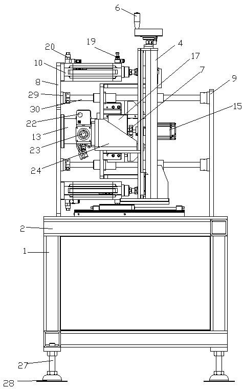
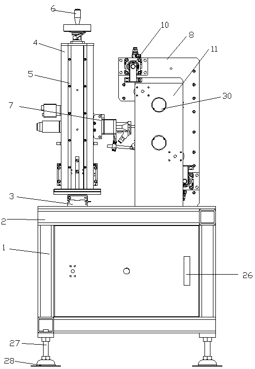
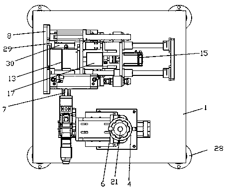
[0022] see Figure 1-4 , a vacuum laser welding device according to an embodiment of the present invention includes an equipment chassis 1, the top of the equipment chassis 1 is provided with a top plate 2, a base 3 is fixed on the top plate 2, and the base 3 is movable A Z-axis lift 4 is connected, a slide rail 5 is provided on the Z-axis lift 4, a stroke handle 6 is provided on the top of the Z-axis lift 4, a laser welding gun 7 is provided on the slide rail 5, and the top plate 2 A first fixing plate 8 and a second fixing plate 9 are arranged on the upper part, and the top and bottom ends of the first fixing plate 8 are provided with a pressure-holding cylinder 10. A first baffle 11 and a second baffle 12 are provided, a guide shaft seat 29 is arranged on the first fixed plate 8 and the second fixed plate 9, and a plurality of guide shafts 30 are arranged on the guide shaft seat 29, Several of the guide shafts 30 pass through the first baffle 11 and the second baffle 12 , ...

Embodiment 2

[0025] see Figure 1-4 , one end of the pressure maintaining cylinder 10 is fixed on the first fixing plate 8 , the first baffle 11 is provided with a support frame 18 , and one end of the support frame 18 is fixed on the pressure maintaining cylinder 10 On the other end, the pressure maintaining cylinder 10 is provided with a valve valve 19 and a safety valve 20 .

[0026] By arranging the valve valve 19 and the safety valve 20, the air pressure in the pressure-holding cylinder 10 can be pressed and released to protect the safety of the device.

Embodiment 3

[0028] see Figure 1-4 , the slide rail 5 is connected with the travel handle 6 through the rotating shaft rod 21 in a rolling connection, the vacuum box 13 is provided with a vacuum box cover 22, the vacuum box cover 22 is provided with an evacuation port 23, the second block A limiting block 24 is provided at one end of the plate 12 close to the pressing cylinder 17 .


PUM


Abstract

The invention discloses a vacuum laser welding device. The vacuum laser welding device comprises an equipment base frame, wherein a Z-axis lifting machine is arranged on the equipment base frame, a laser welding gun is arranged on the Z-axis lifting machine, a first fixation plate and a second fixation plate are arranged on the base frame, a pressure maintaining air cylinder is arranged at the topend of the first fixation plate, a first stopping plate and a second stopping plate are arranged between the first fixation plate and the second fixation plate, guide shafts are arranged on the firstfixation plate and the second fixation plate, a vacuum box is fixed to the first fixation plate, a servo motor is arranged on the second baffle, the output end of the servo motor runs through the second baffle and is connected with a coupler, and the pressure maintaining air cylinder is arranged at one end of the coupler. The vacuum laser welding device is simple in structure and convenient to weld, contact with air is reduced, oxidation of the product is lowered, welding is more uniform, and the product is prevented from being deformed or cracked.

Description

technical field [0001] The invention relates to the technical field of vacuum equipment for laser welding, in particular to a vacuum laser welding device. Background technique [0002] As an efficient, high-quality and green processing tool, laser welding is widely used in various fields of industrial production such as ships, rail transit, aerospace, etc. The penetration depth, that is, the depth of the molten pool, is one of the most important indicators for evaluating its quality. In recent years, with the emergence of high-power fiber lasers and disk lasers, vacuum laser welding technology has also developed rapidly. The vacuum environment has a good effect on suppressing plasma. Under the same power, laser welding in atmospheric environment can be obtained. 2 ~3 times the penetration depth at the seam, or the same penetration depth can be achieved with less laser power, and the seam is uniform and beautiful [0003] In the prior art, laser welding is affected by comp...

Claims


Application Information

Patent Timeline
Patent Type & Authority Applications(China)
IPC IPC(8): B23K26/21B23K26/12B23K26/70
CPCB23K26/21B23K26/12B23K26/70B23K26/1224B23K26/702
Inventor 崔文豪王茁荟
Owner 上海百善实业发展有限公司
Why Eureka
Try Eureka