
Surround members for stainless steel pipe cutting

A technology for pipe cutting and stainless steel, which is applied in the direction of pipe shearing devices, shearing devices, and attachments of shearing machines, etc., which can solve the problems of wasting pipe fitting materials, cutting end faces that are difficult to reach flat, and wasting time for operators, so as to avoid waste , high flatness and ingenious structure

Active Publication Date: 2021-07-16
浙江天赐泵业股份有限公司
View PDF12 Cites 0 Cited by
  • Summary
  • Abstract
  • Description
  • Claims
  • Application Information

AI Technical Summary

Problems solved by technology

[0002] Existing ordinary cutting machines cut pipe fittings, and there are obvious disadvantages. Specifically, when cutting pipe fittings through cutting blades, the cut end faces are difficult to achieve flatness, so after cutting, the cut end faces need to be trimmed. On the one hand It wastes the time of the operators, and on the other hand, it will waste a certain amount of pipe fitting materials, especially when cutting large-diameter pipe fittings, this technical problem is more prominent. In order to overcome the above-mentioned disadvantages, it is necessary to Provides a surrounding cutting member for pipe fittings with ingenious structure, simple principle, convenient operation and use, high degree of automation, and high flatness of the cutting end surface

Method used


Image

  • Surround members for stainless steel pipe cutting
  • Surround members for stainless steel pipe cutting
  • Surround members for stainless steel pipe cutting

Examples


Embodiment Construction

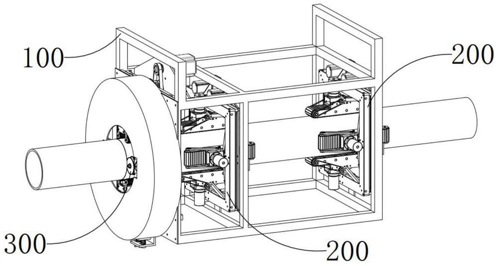
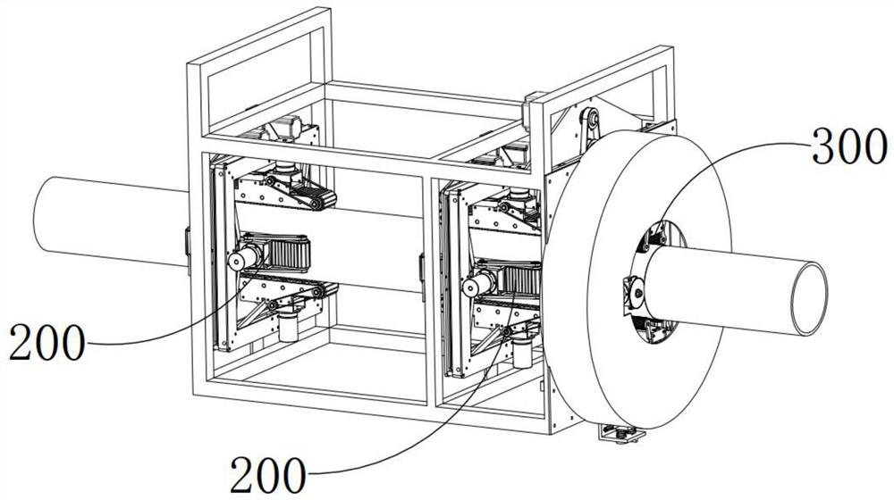
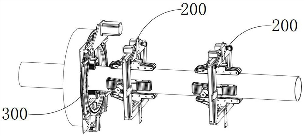
[0049] see Figure 1-26 , a double-saw surround pipe cutting machine, which includes a mounting frame 100, a clamping and feeding device 200, and a surrounding cutting device 300. There are two clamping and feeding devices 200 arranged front and rear and fixedly installed on the mounting frame 100. The surrounding cutting device 300 is also fixedly installed on the mounting frame 100 and one of the clamping and feeding devices 200 is located between the other clamping and feeding device 200 and the surrounding cutting device 300. The middle position of the clamping and feeding device 200 and the surrounding cutting device 300 can allow the tube Passing through, the clamping and feeding device 200 can guide and clamp the penetrating pipe and feed it towards the surrounding cutting device 300, and the surrounding cutting device 300 can cut the passing pipe. The clamping and feeding device 200 includes The clamping part 210 and the box-shaped driving part 220, the clamping part 2...


PUM


Abstract

The invention provides a surrounding component for cutting stainless steel pipes, a cutting mechanism, a pressing mechanism, a driving part, a rotating driving mechanism and a through hole slip ring assembly. The cutting mechanism is arranged on the inner side of the square frame-shaped driving part and two symmetrical Two pressing mechanisms are arranged on the inner side of the driving part and there are two symmetrically arranged. The driving part can drive the cutting mechanism to move closer to each other, and can drive the pressing mechanism to move closer to each other and make it hold the passing pipe. , the rotary drive mechanism can drive the drive component, cutting mechanism, and pressing mechanism to rotate synchronously around the axial direction of the pipe. The remarkable thing is that two cutting blades are used to cut the pipe around, that is, the cutting blade can rotate around its own axial direction. While rotating around the axial direction of the pipe fittings, the cutting blades move close to each other to achieve radial feeding. The end face after cutting has high flatness and does not need repeated trimming, which avoids the waste of pipe fitting materials.

Description

technical field [0001] The invention relates to a cutting machine, in particular to a surrounding member for cutting stainless steel pipes. Background technique [0002] Existing ordinary cutting machines cut pipe fittings, and there are obvious disadvantages. Specifically, when cutting pipe fittings through cutting blades, the cut end faces are difficult to achieve flatness, so after cutting, the cut end faces need to be trimmed. On the one hand It wastes the time of the operators, and on the other hand, it will waste a certain amount of pipe fitting materials, especially when cutting large-diameter pipe fittings, this technical problem is more prominent. In order to overcome the above-mentioned disadvantages, it is necessary to The invention provides a surrounding cutting member for pipe fittings with ingenious structure, simple principle, convenient operation and use, high degree of automation, and high flatness of the cutting end surface. Contents of the invention [...

Claims


Application Information

Patent Timeline
Patent Type & Authority Patents(China)
IPC IPC(8): B23D21/04B23D33/00B23D33/02
CPCB23D21/04B23D33/00B23D33/02
Inventor 袁智
Owner 浙江天赐泵业股份有限公司
Learn More